BIG A-5 Vigilante build
 02-11-2019, 05:04 PM
#551

My Feedback: (20)
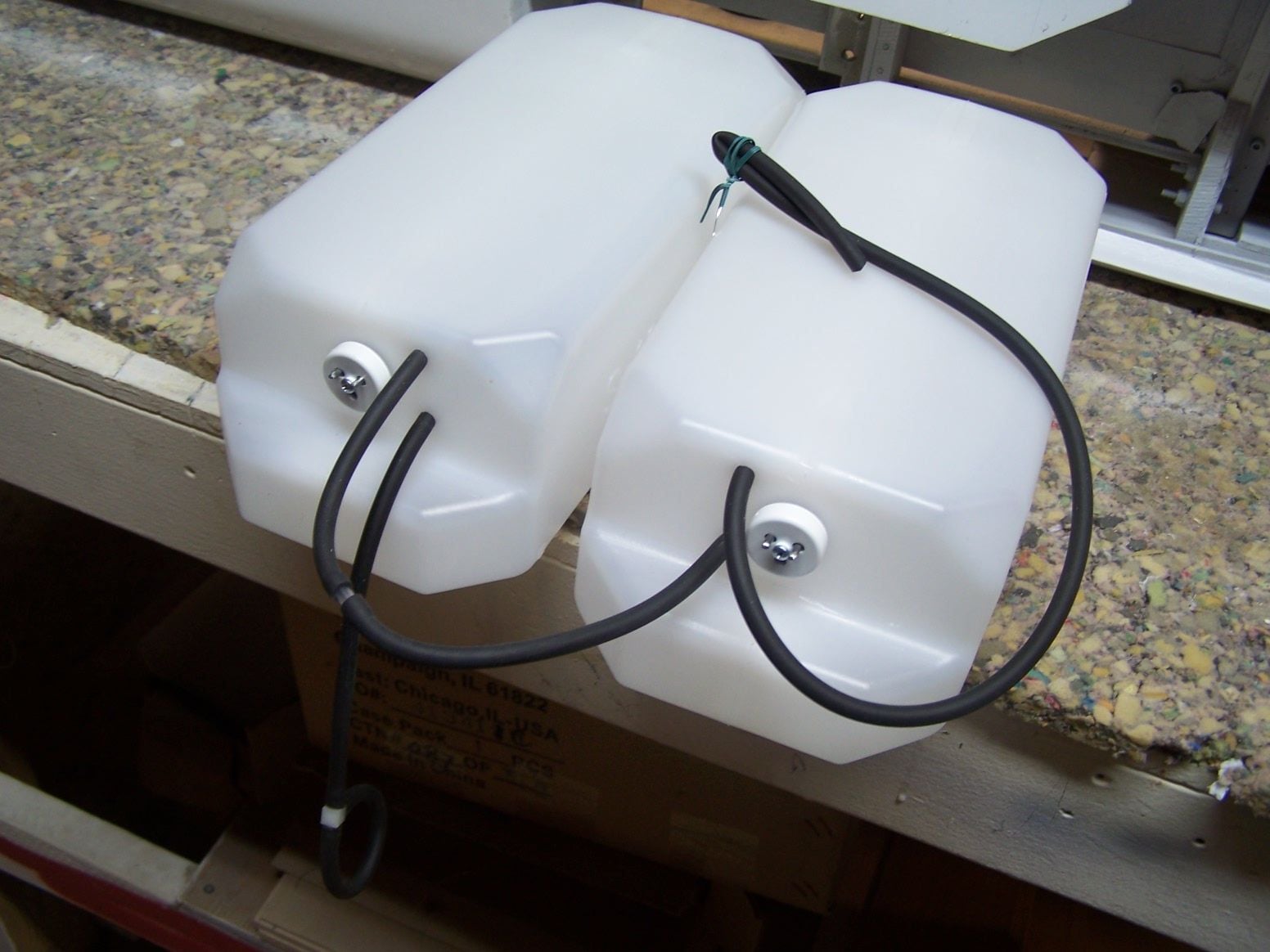
Yikes, I have to agree with Jeremy about the friction fit tubes in the Dubro tanks. I did vents through the Dubro tanks several years ago but I used a threaded barbed brass fitting from B & B sealed with hysol. I got away with it then but would prefer not to do it again.
 02-11-2019, 06:23 PM
#552
Thread Starter
Join Date: Mar 2009
Location: willow springs , IL
Posts: 1,212
Likes: 0
Received 25 Likes
on
14 Posts
Thanks LGM for your thoughts. I will monitor the fuel lines and tanks closely. They will be in direct sight with the top hatch off............ Here is how I adopted this method. Many years ago I took apart a craftsman weedwacker. I found the fuel lines into the tank were also friction fitted. I thought how can they be doing this on thousands and thousands of weed wackers that were holding gas and being kept in peoples garages and basements? Well my answer was one of two possibilities, the money they save on brass fittings was worth blowing up a couple of houses, or because it works. So I tried it on a couple of small glow tanks with silicone tubing. This would eliminate the corroding green brass tubes.To my delight it worked just fine. I thought to myself you could make a tank out of any bottle, so I did. My favorite is a 12 oz. saline solution bottle for my combat airplane. The next was for my Ziroli warbirds. I ran Tygon through the side of a 32 oz. Dubro tank. IT DID NOT WORK!. After a short time the Tygon formed a memory and lost the friction fit. A bit later I was informed about neoprene gas line with Viton. It was a miracle fuel line that would never get stiff in a tank. I bought some but it wasn't cheap, about $4 a foot. So the Viton went back through the side of the 32oz. Dubro tank I ruined by drilling holes in the side of it. The tank went back in the plane. It is still holding today after many years, along with a half a dozen other warbirds and a few jets with the same tank setups. If you look above at post 541 my Boomerang fuel tank (maple syrup bottle) started to split at the seam after 13 years. The friction fits were still holding and the old Viton went back in the new tank / syrup bottle. And thats the trials and errors I went through with this method. It seems to work for me so I stuck with it. If anything changes Ill put up a post...........As a side note this method also works great on air tanks made out of soda bottles. Drill the undersized hole through the cap though and not the side of the soda bottle. The bottle will fail, at a crazy high pressure, before the friction fit leaks.

 02-13-2019, 06:19 AM
#554
Thread Starter
Join Date: Mar 2009
Location: willow springs , IL
Posts: 1,212
Likes: 0
Received 25 Likes
on
14 Posts
Hi Mike I never tried it through a fiberglass tank. They seem a lot thinner. I don't know if you would be able to drill a nice clean hole. Any polyethylene bottle would work as long as the area to drill through is relatively thick. The other thing is you will need to take a few minutes to clean the shavings out of the tank and the burrs around the hole. Try it on a little glow plane with silicone tubing to get the hang of it. With gas or diesel you can only use Viton tubing.
02-23-2019, 05:56 PM
#555
Thread Starter
Join Date: Mar 2009
Location: willow springs , IL
Posts: 1,212
Likes: 0
Received 25 Likes
on
14 Posts
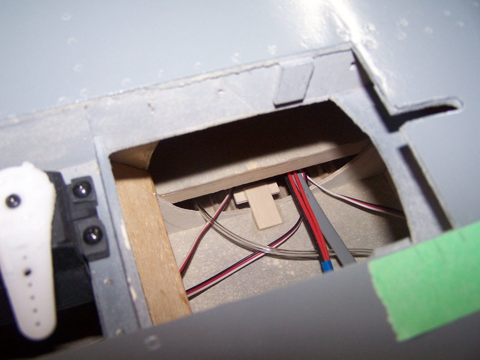
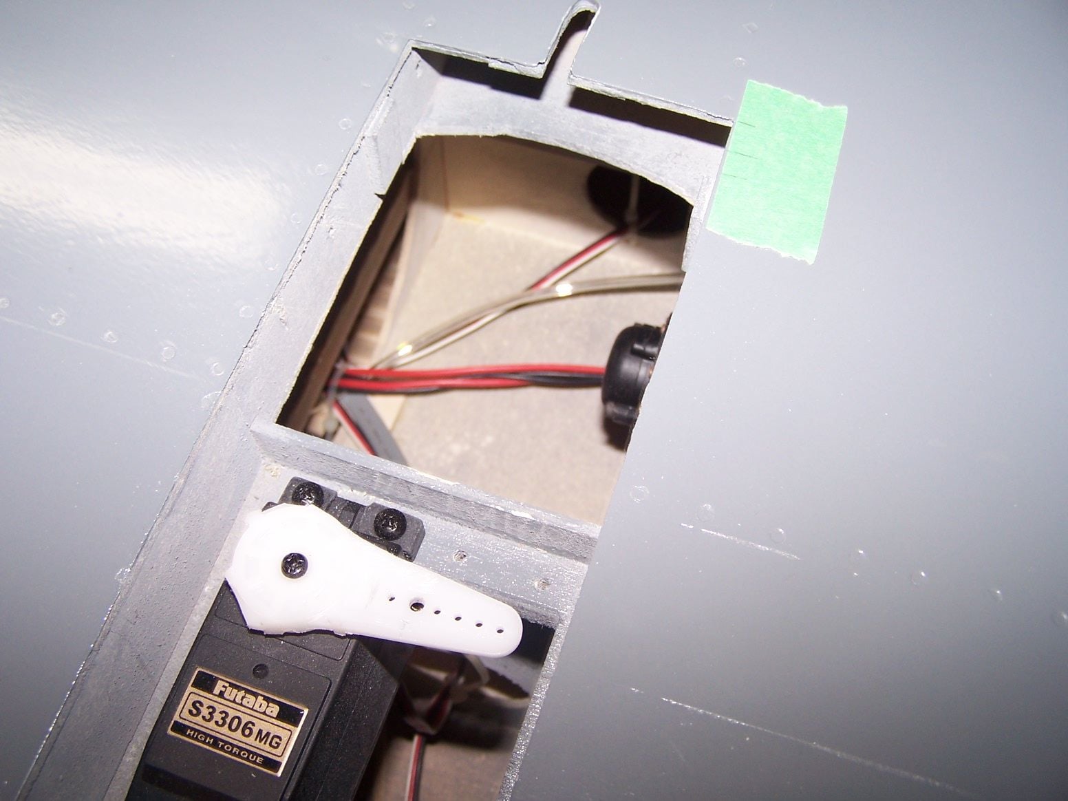
One more thing, bevel cutting the fuel line makes it easier to force through the undersized holes...........................I made an electrical extension for the turbine since the original was too short and the locking tab on the RJ 45 plug was broken off. the plug would not stay in the turbine. The wires will come up with the fuel lines and the other servo wires. i may have a line on a hobby king hydraulic landing gear controller for Vladimir's gear.
03-04-2019, 10:30 PM
#556
Thread Starter
Join Date: Mar 2009
Location: willow springs , IL
Posts: 1,212
Likes: 0
Received 25 Likes
on
14 Posts

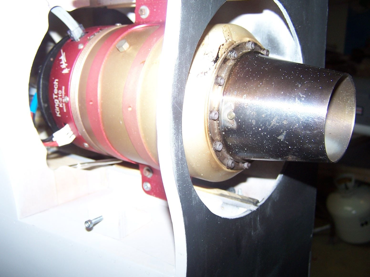
I bought some nice 18 gauge silicone wire from Value Hobbies and made a custom extension from the ECU back to the engine. It came out nice. Much more flexible than the 20 gauge vinyl wires that come with the engine. I may make a custom harness from the battery to the ECU to the pump. The tray is getting crowded with batteries. Although the landing gear hydraulic pump battery may get installed near the pump.
03-09-2019, 09:19 PM
#557
Thread Starter
Join Date: Mar 2009
Location: willow springs , IL
Posts: 1,212
Likes: 0
Received 25 Likes
on
14 Posts
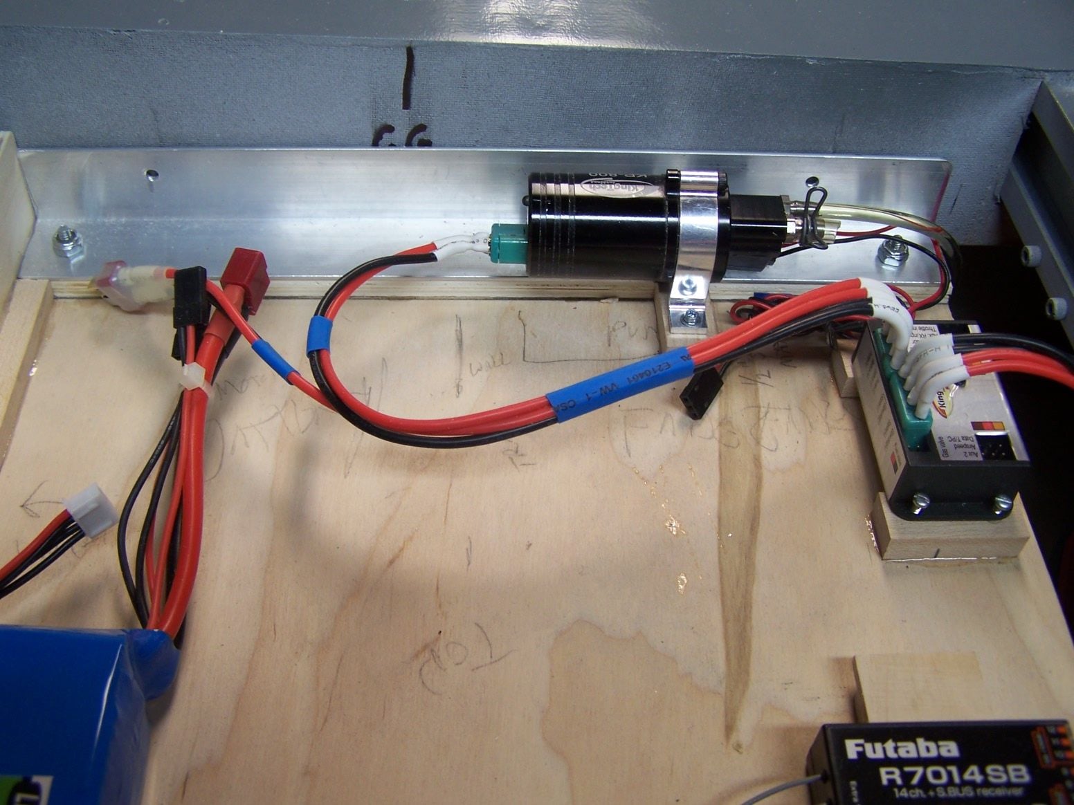
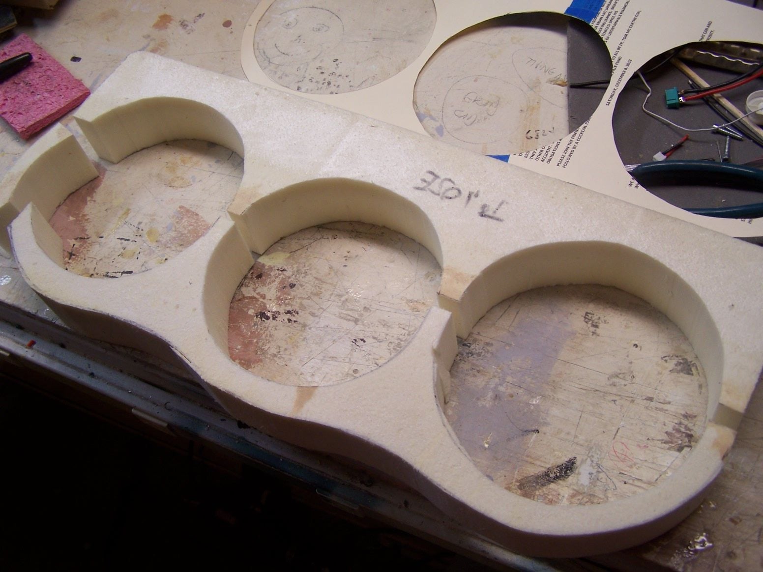
I made the custom sized harness from the battery to the ECU to the pump. Heavier wire, more flexible, cleaner install. The white heat shrink got a little bend when it was still hot to get the wires going in the right direction. I cut some urethane foam for the back to the fuse to start messing around with the fairings back there. I messed around with my 14 FG and figured out how to mix the flaps with the ailevators. I feel better knowing I have some roll control on the wings.
03-10-2019, 09:06 PM
#558
Thread Starter
Join Date: Mar 2009
Location: willow springs , IL
Posts: 1,212
Likes: 0
Received 25 Likes
on
14 Posts
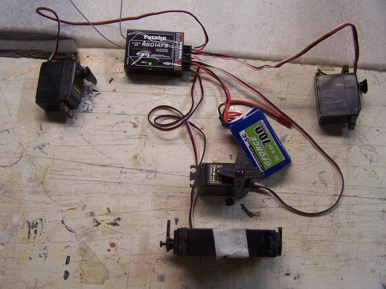
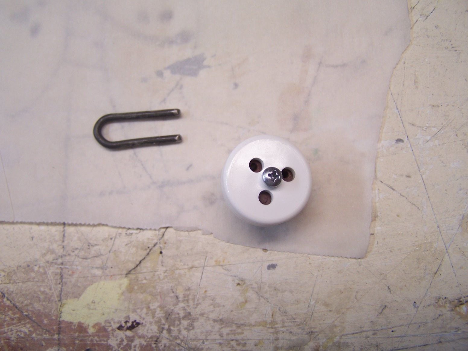
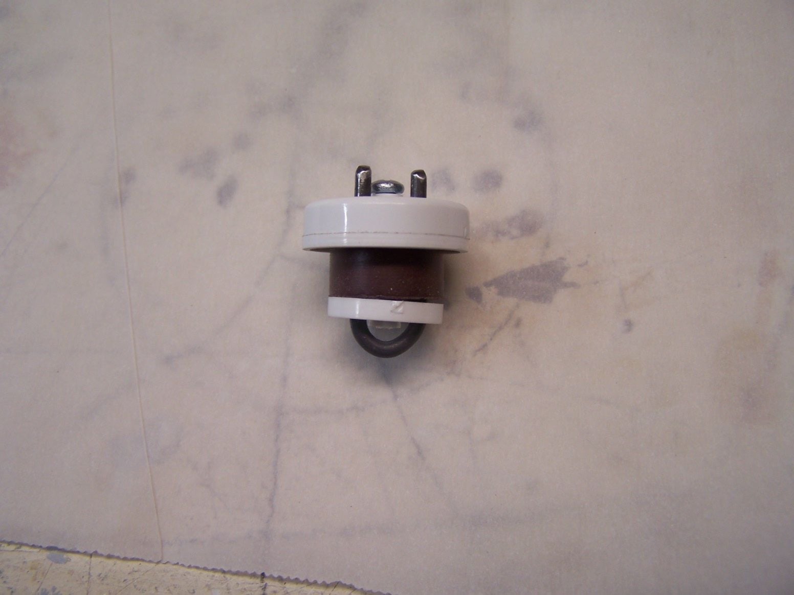
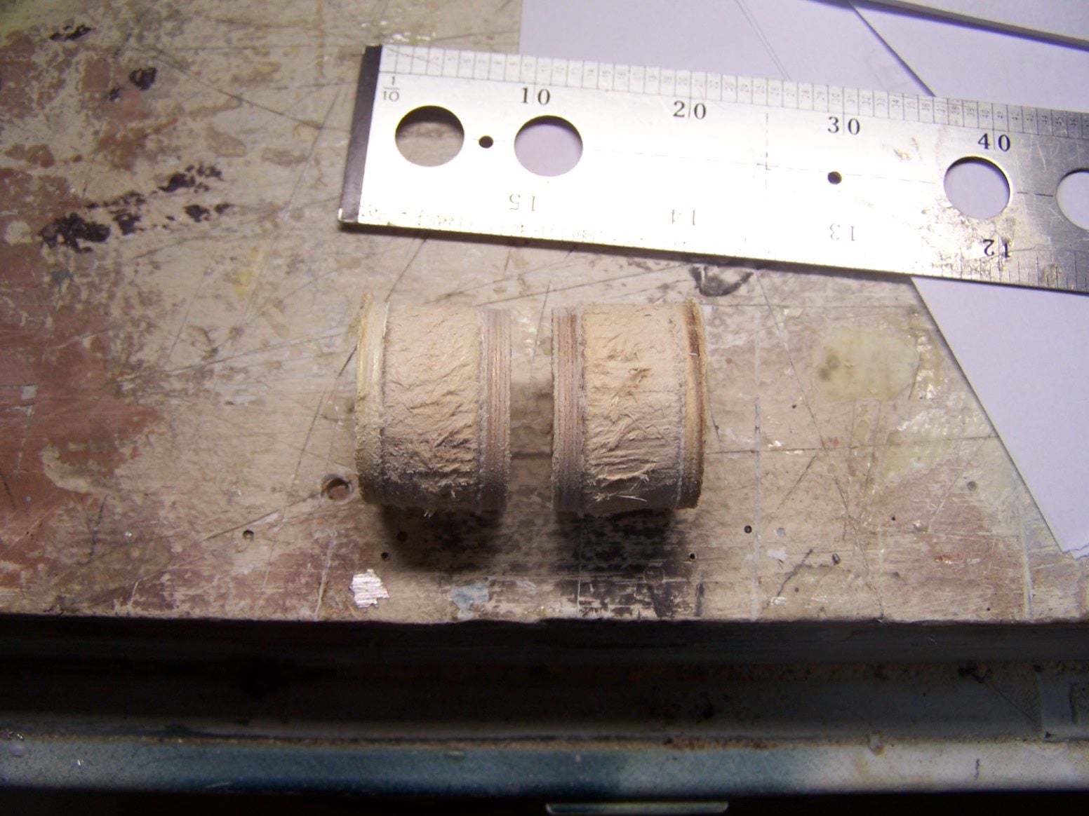
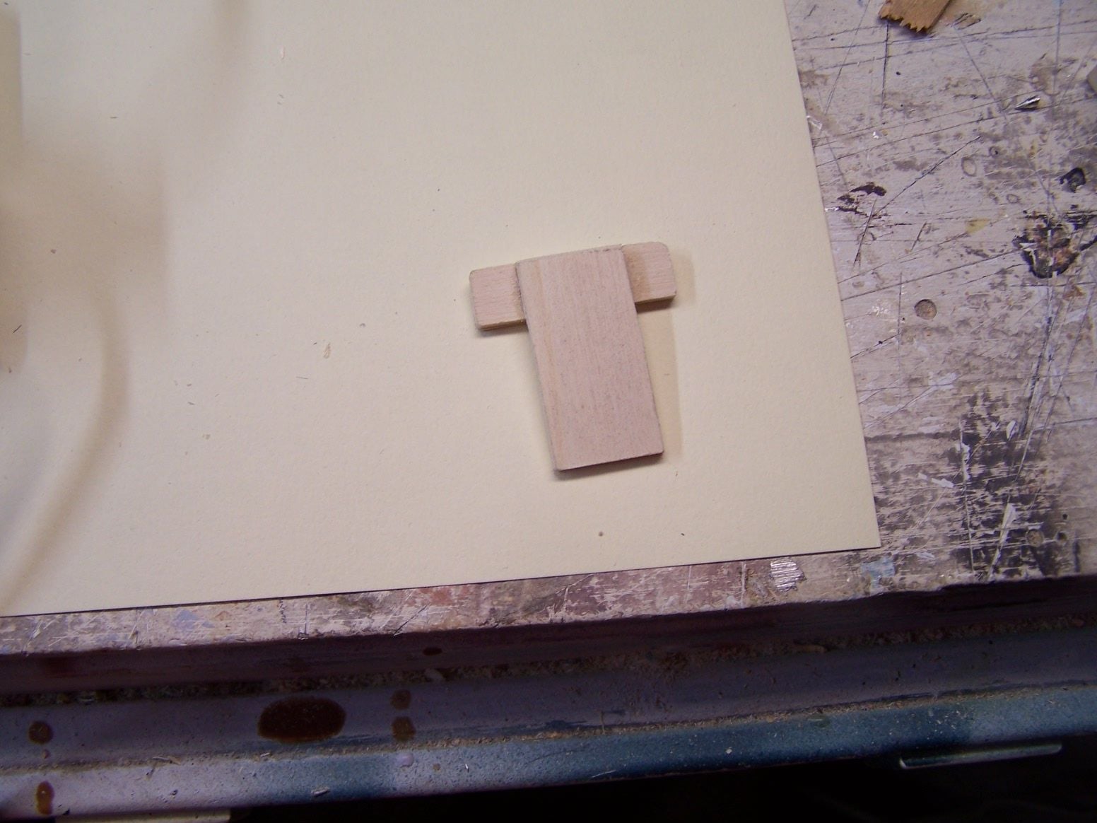
I set up some servos to test their movement before I plug in anything on the plane....Since there are no tubes running through the fuel tank stoppers I made some horse shoes to plug the holes and stop things from rotating when they are tightened.
03-16-2019, 08:50 AM
#559
Thread Starter
Join Date: Mar 2009
Location: willow springs , IL
Posts: 1,212
Likes: 0
Received 25 Likes
on
14 Posts
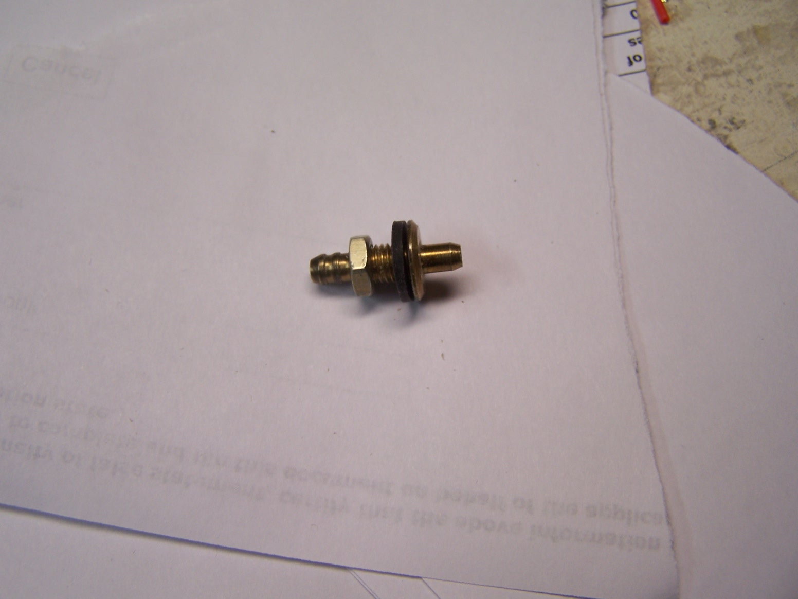
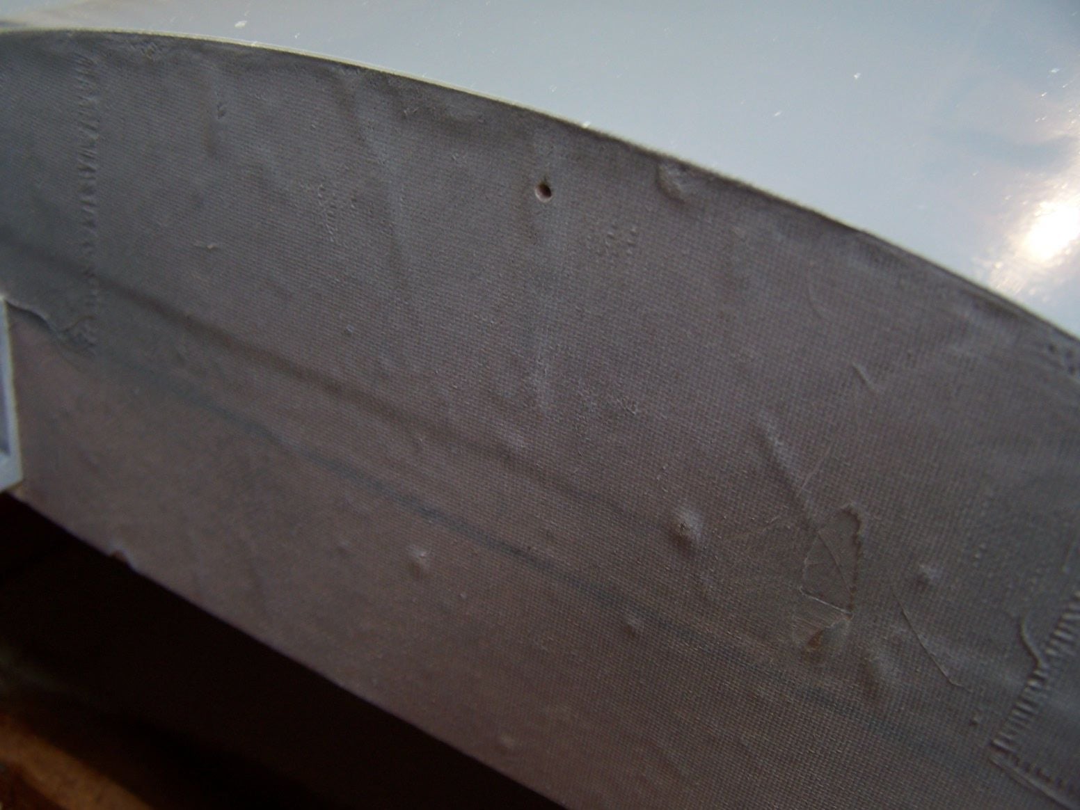
Vladimir made a nice overflow fitting.

So I decided to mount it in the wheel well.

I drilled a pilot hole through the two nose mounting plates before I installed them. I decided to hole saw an opening through them.
They are composite sandwich. Aircraft ply, 6 oz glass, balsa wood, 6oz glass, and lite ply.
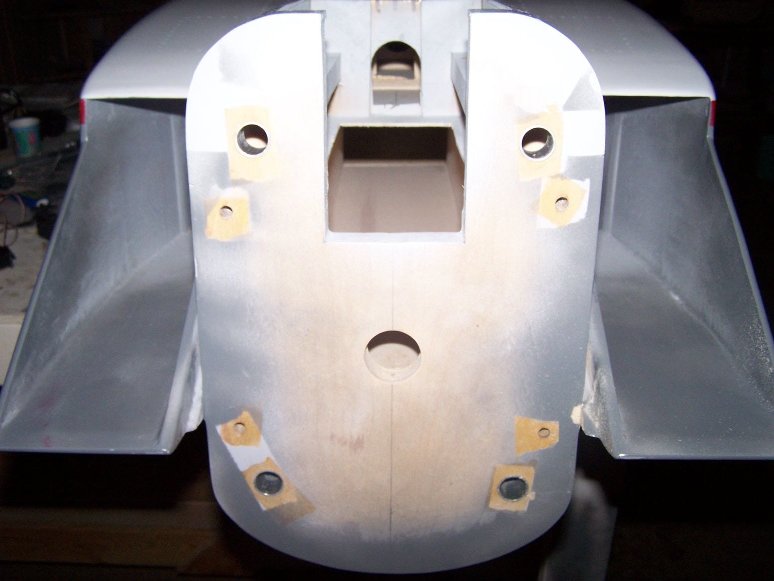
In case I need to mount something in the nose and run hoses or wires.
03-18-2019, 08:18 PM
#560
Thread Starter
Join Date: Mar 2009
Location: willow springs , IL
Posts: 1,212
Likes: 0
Received 25 Likes
on
14 Posts
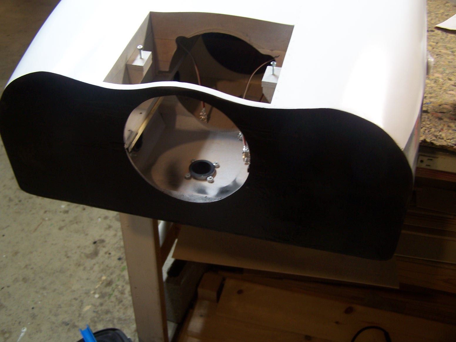
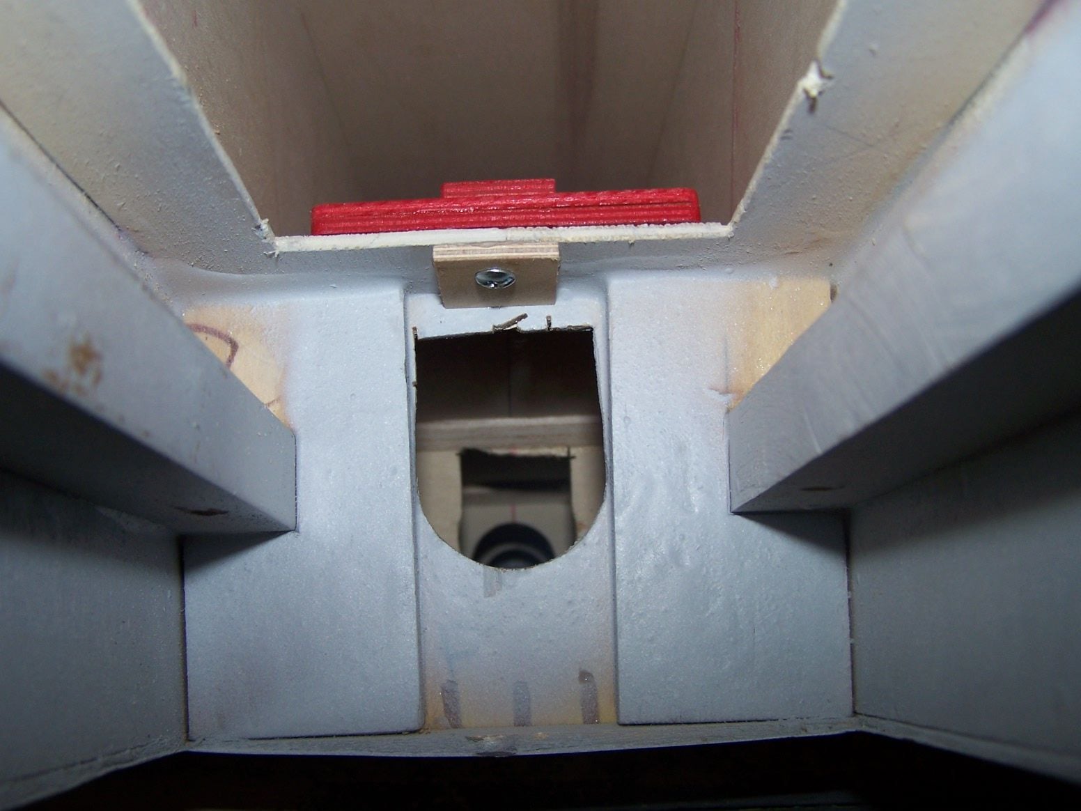
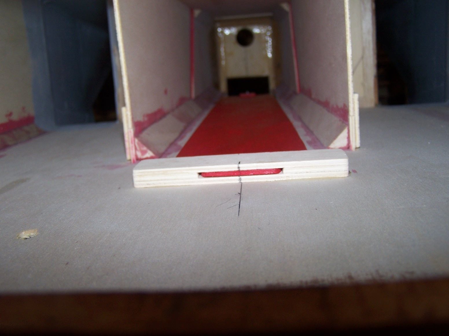
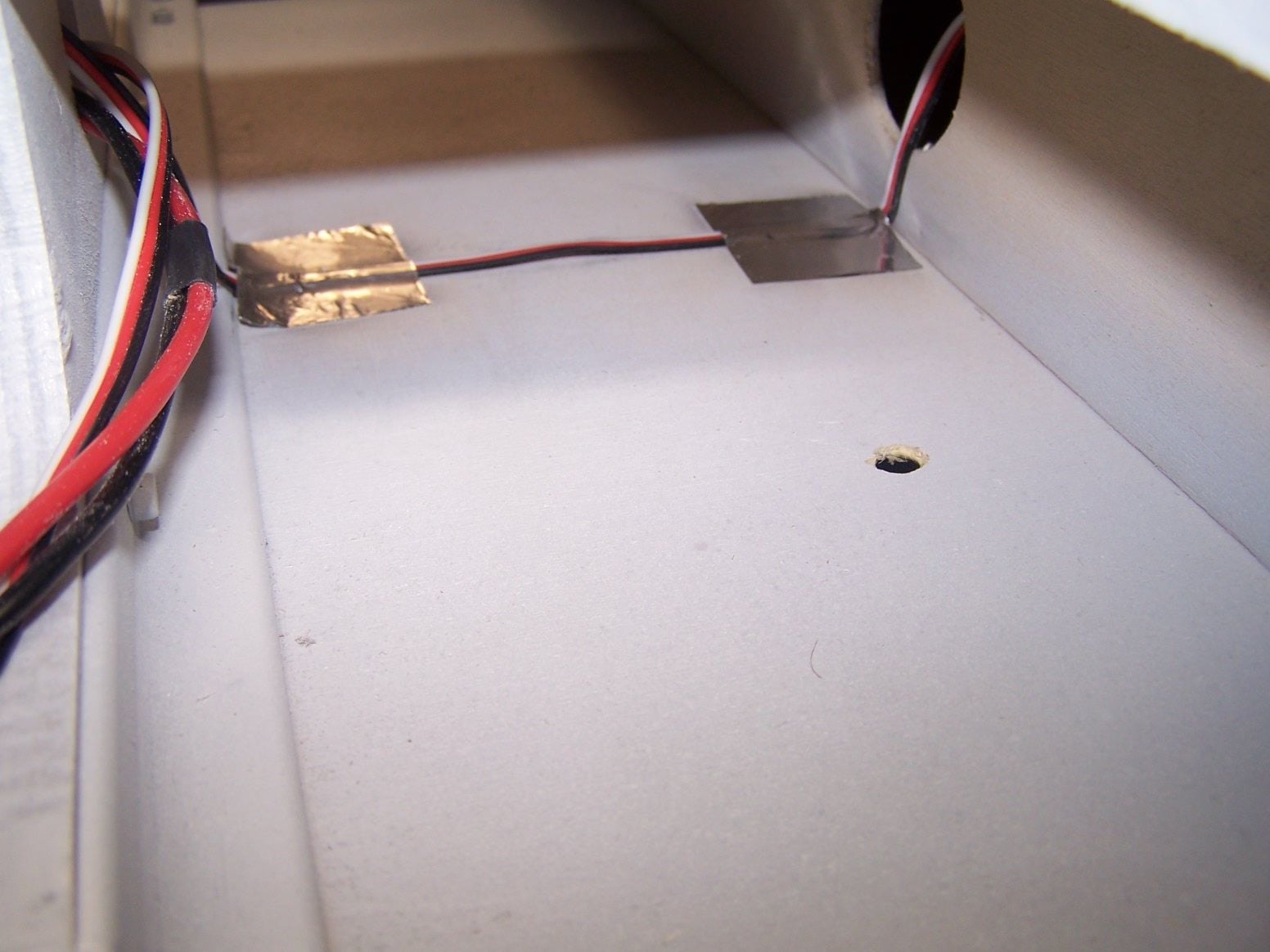
I blacked out the back on the fuse for the time being
The stop on the landing gear is just about flush with the outside of the fuse. So I cut a hole in the door to start messing around with some hinging

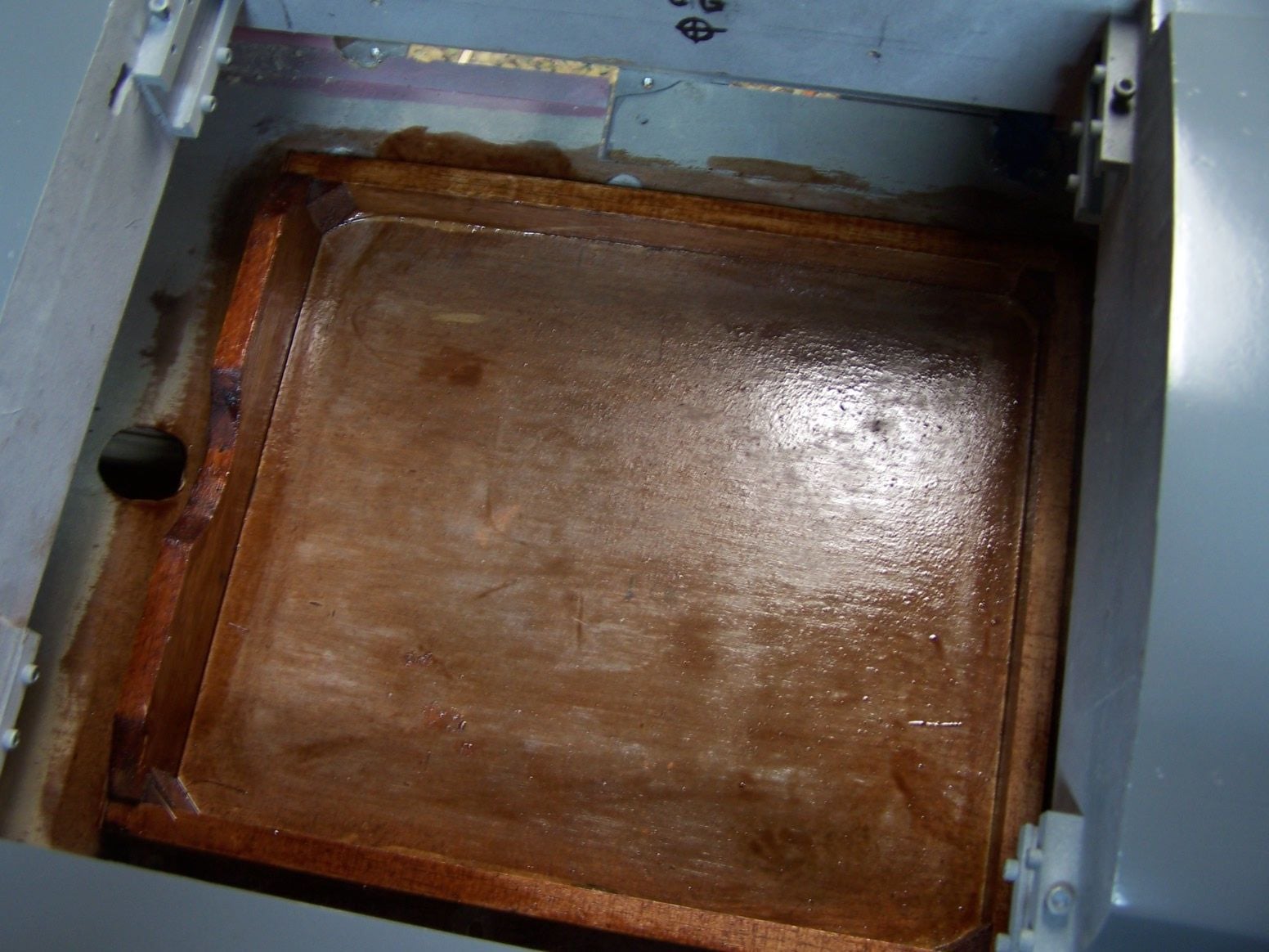
I fuel proofed the tank floor with some epoxy.
03-18-2019, 08:32 PM
#561
Thread Starter
Join Date: Mar 2009
Location: willow springs , IL
Posts: 1,212
Likes: 0
Received 25 Likes
on
14 Posts
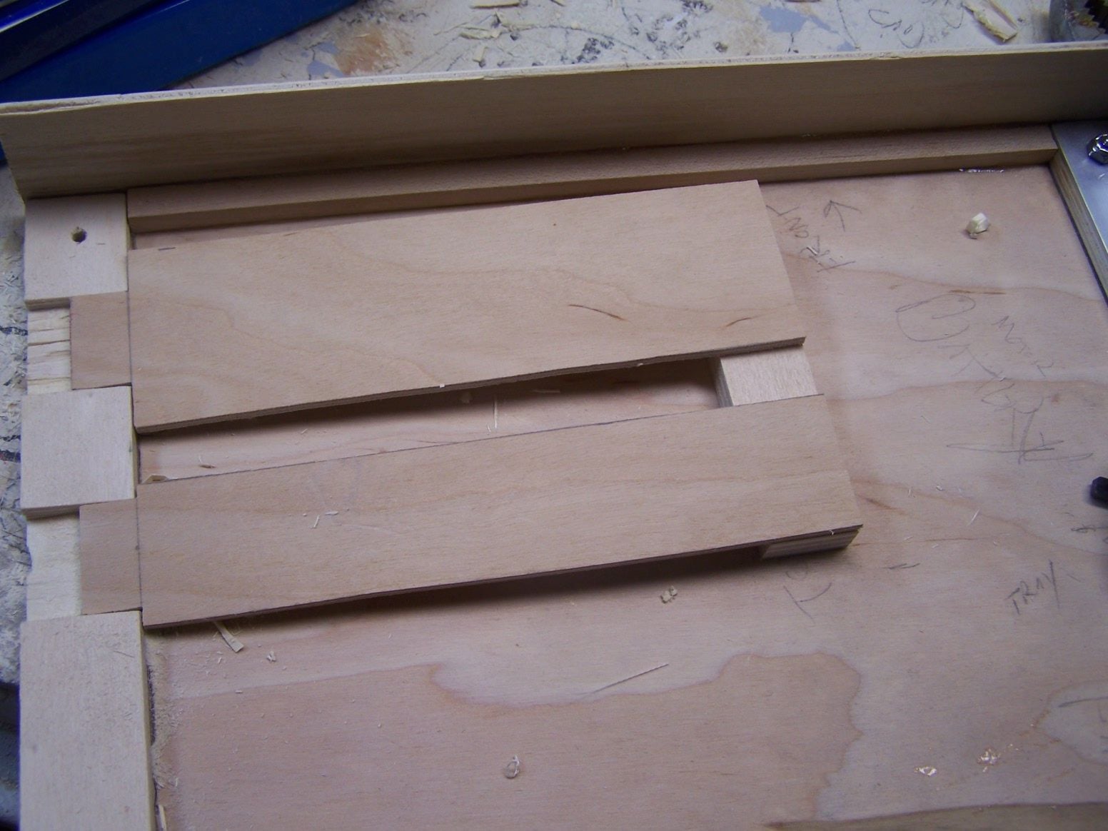
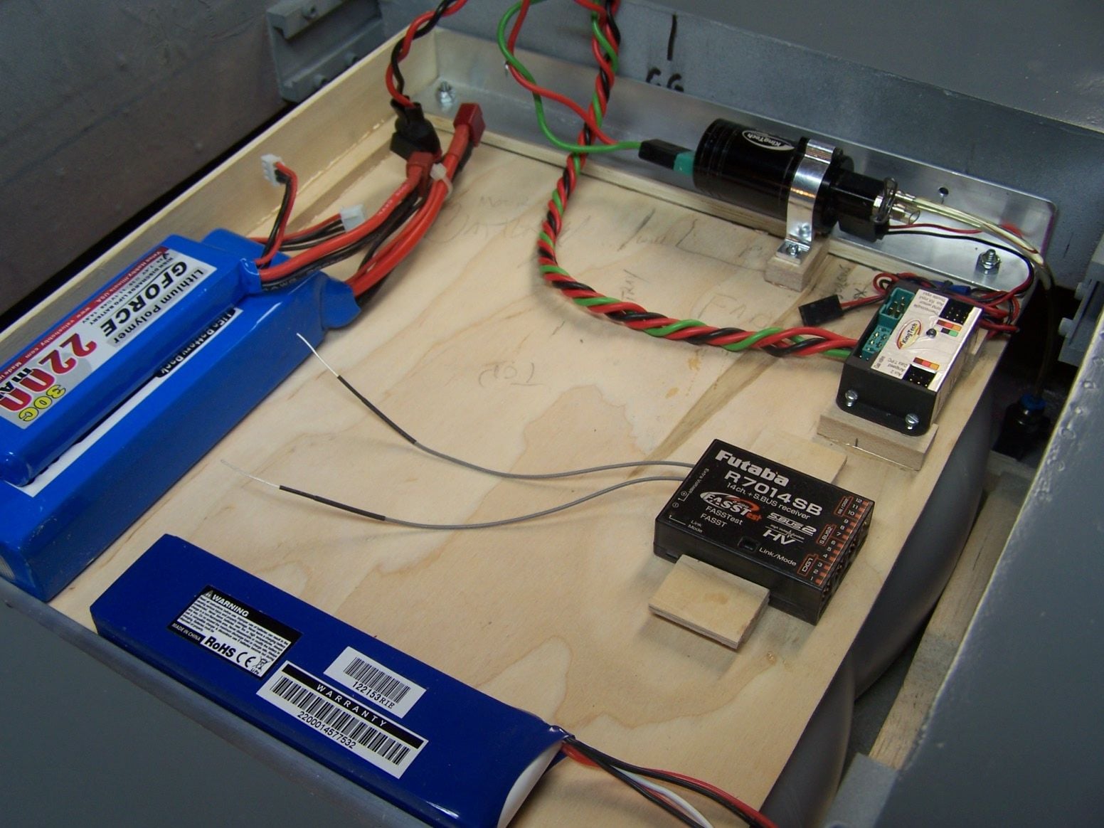
I notched out the wood under the aluminum to accept the tongues of the battery trays.
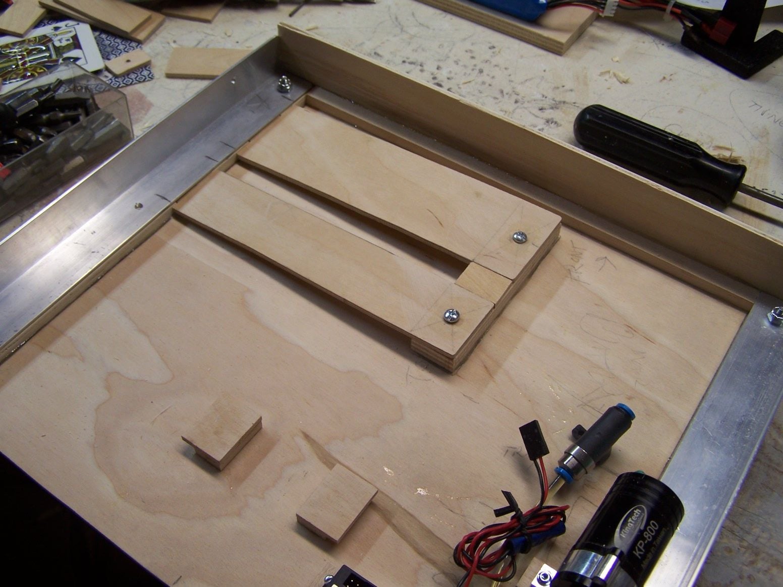
The trays run up on an angle to a block to screw into. Nothing can screw through the bottom of the deck because the fuel tanks are immediately under it.
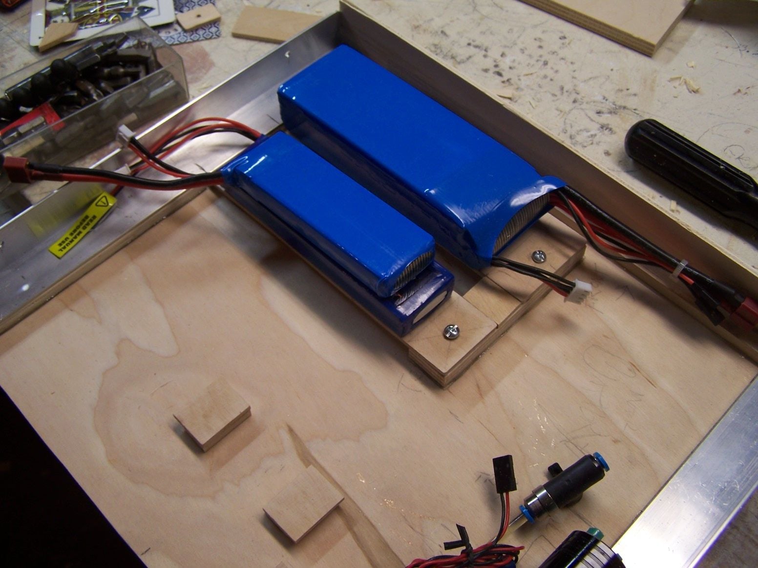
One screw to remove a battery. The idea was to mount the batteries and take up as little real estate as possible. I also glued down two small chocks to hold the receiver.
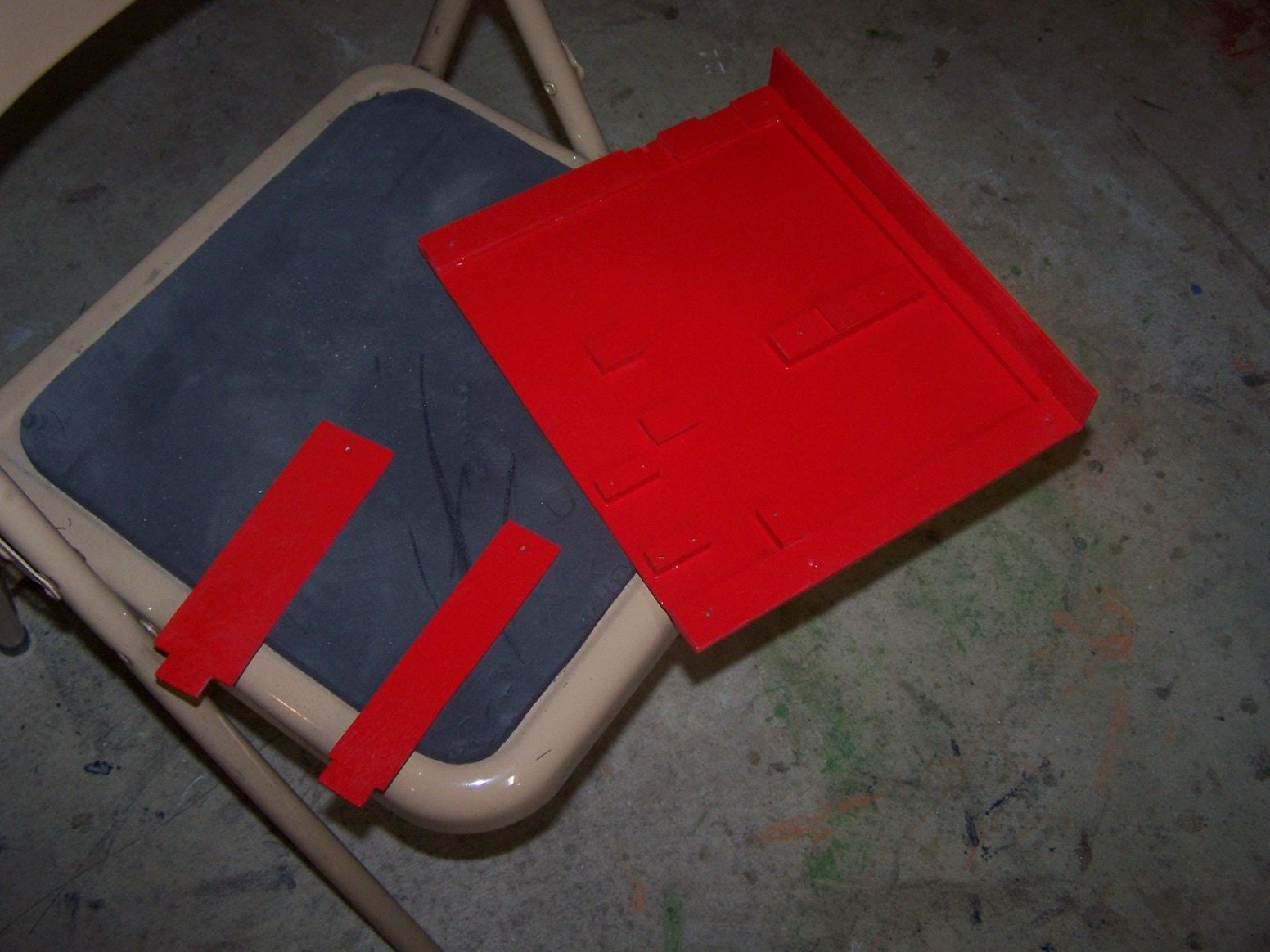
I squirted some red paint on everything to make it look nice. It was left over from the red intake wedge on the outside of the fuse.
03-21-2019, 06:12 AM
#562
Thread Starter
Join Date: Mar 2009
Location: willow springs , IL
Posts: 1,212
Likes: 0
Received 25 Likes
on
14 Posts
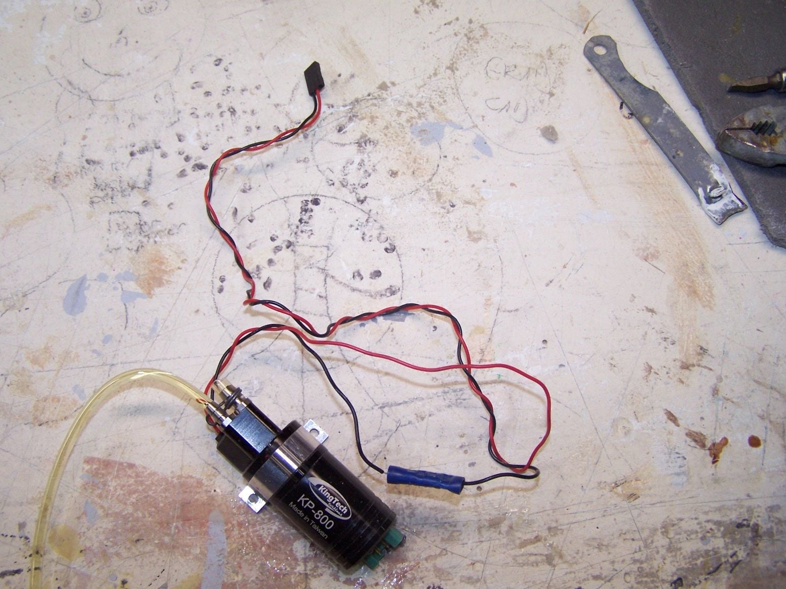
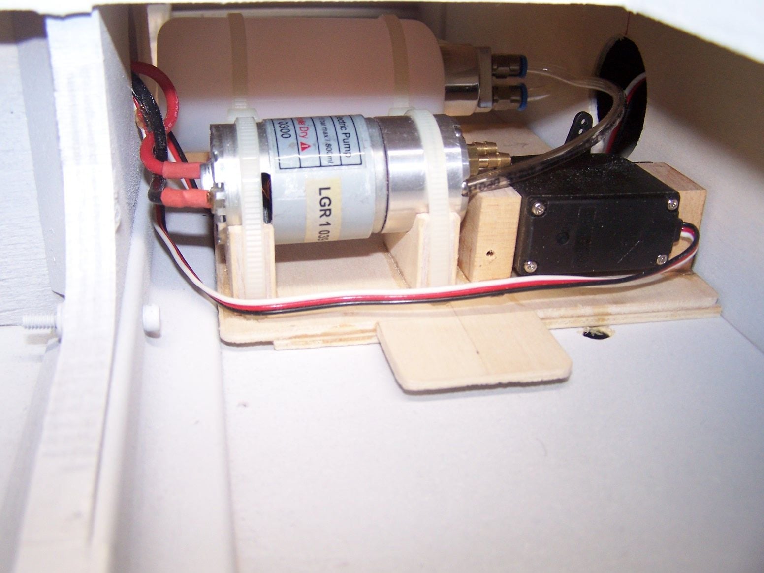
the pump solenoid had a very long lead with a squeeze connector. I light tug pulled the wire out. So I trimmed it down for a neater soldered install
I moved the pump back to make room for a shut off valve. I will build up a little stand to secure the valve.
I pressure tested the tanks by blowing in them and pinching the line. One small leak by the bung. It stopped with a screw turn. I am always concerned about over tightening. They held pressure overnight.
I vacuumed and blew out the fuse with air rotating it as I went. I got out a cloud of saw dust and debris from building. I will blow it out one more time before I start the engine. If there is anything left behind it will be up to the for screen to catch.
03-21-2019, 07:23 PM
#563
Thread Starter
Join Date: Mar 2009
Location: willow springs , IL
Posts: 1,212
Likes: 0
Received 25 Likes
on
14 Posts
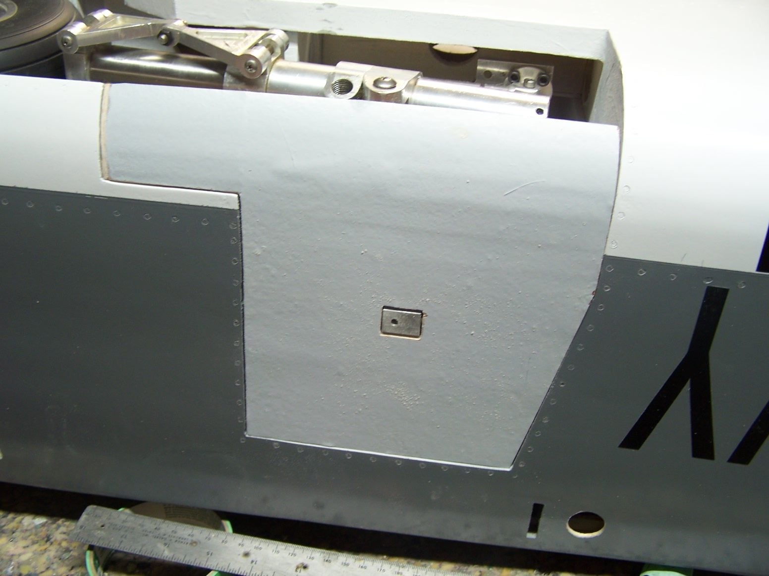
I drilled a hole for the hatch pin and it drilled really easy. I suspected I drilled into a balsa stringer.
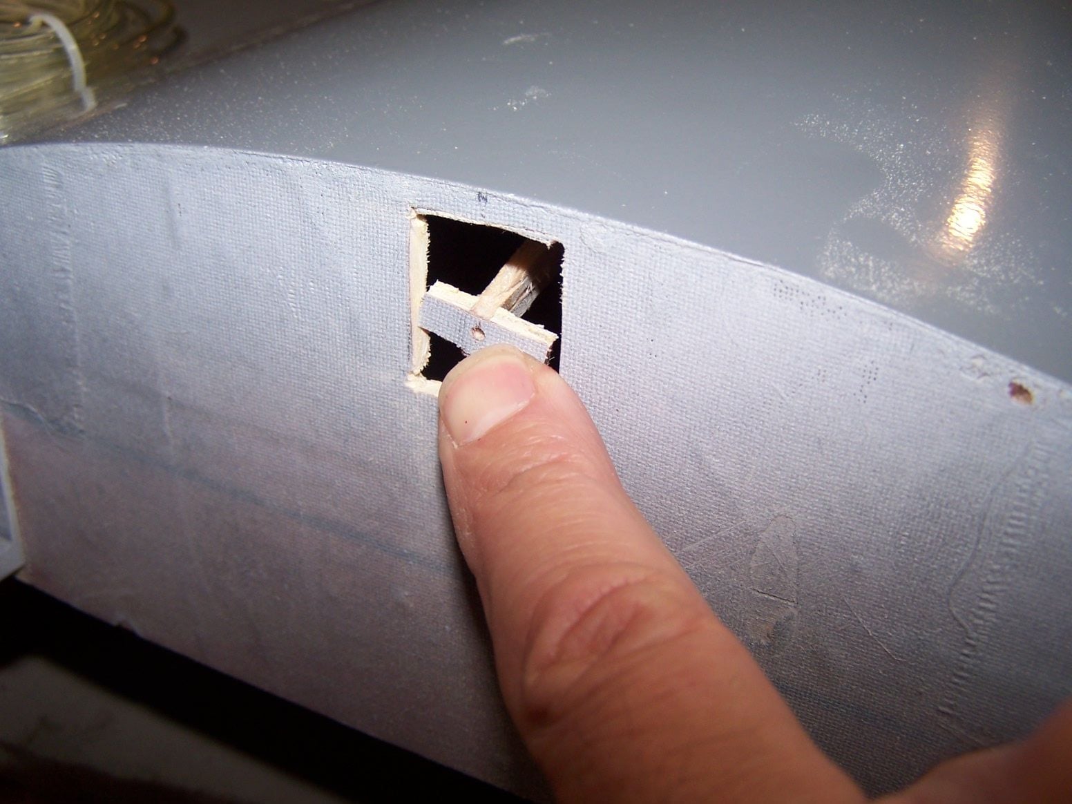
Sure enough I did. Talk about everything being on the center line, I was amazed.
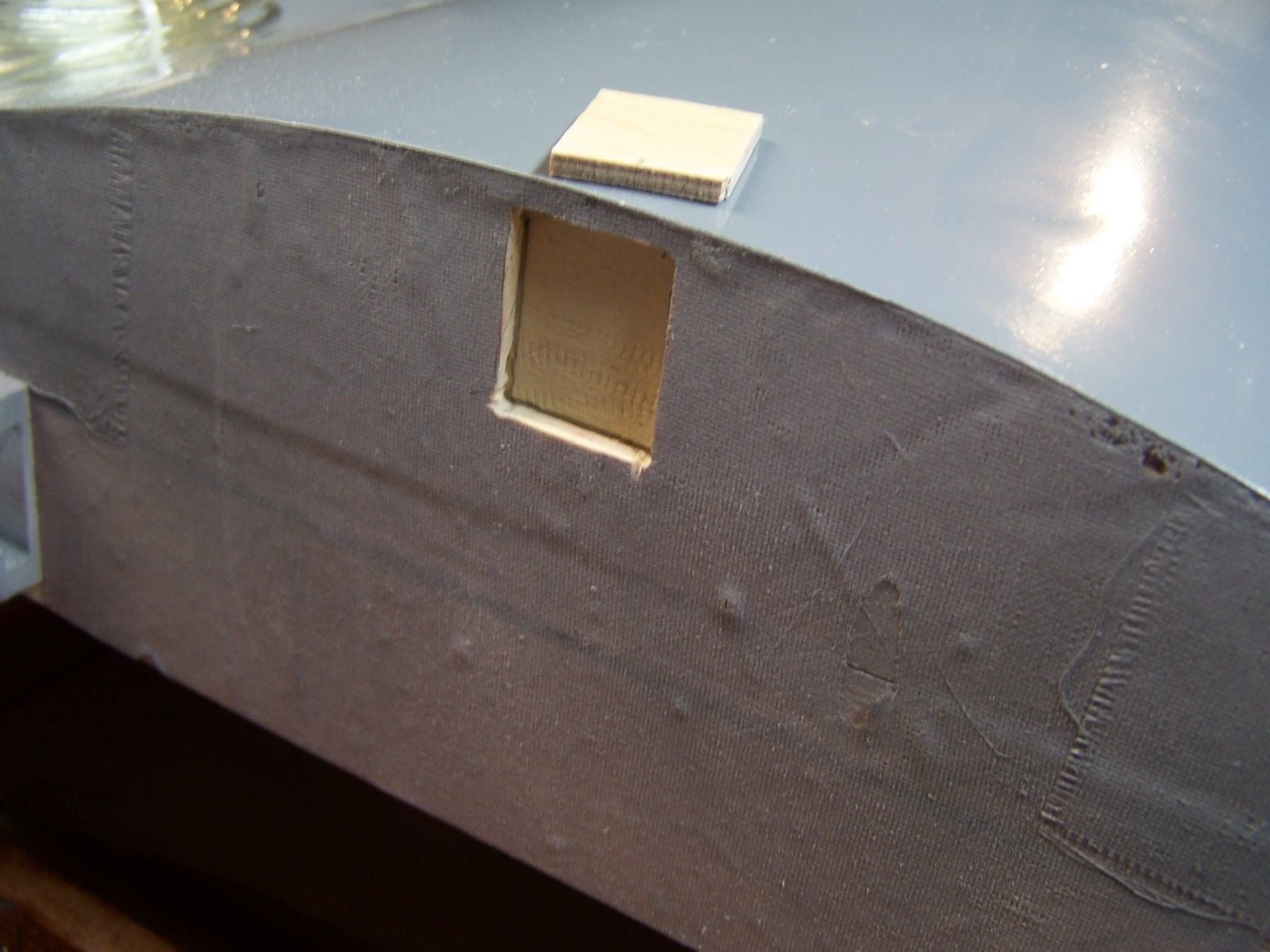
I backed the cut out with light ply and will fill the hole with some aircraft ply to give the hatch pin something to hold in.
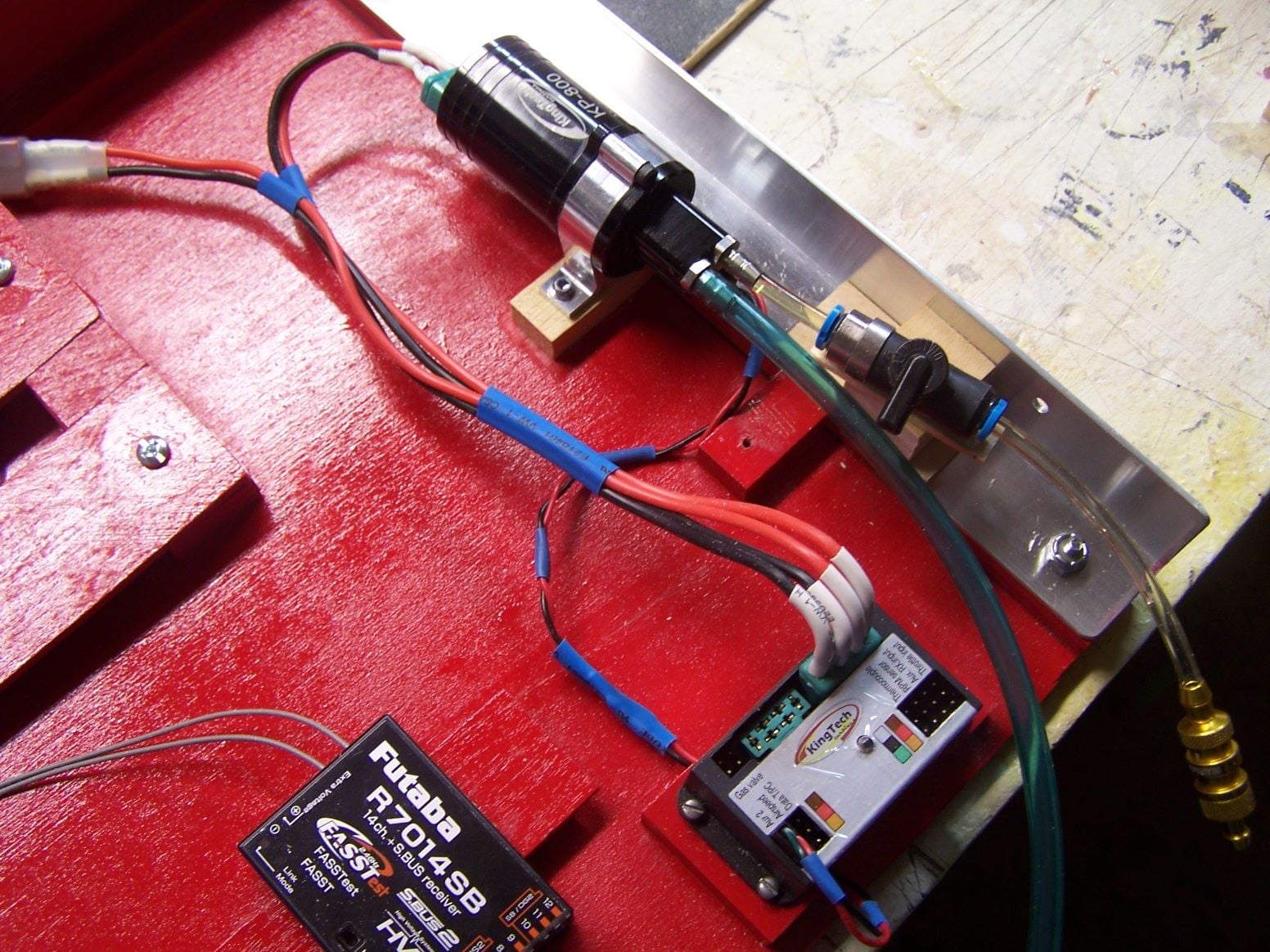
A little stand off to zip tie the shut off valve down. Top piece is a high tech popsicle stick.
03-24-2019, 07:21 PM
#564
Thread Starter
Join Date: Mar 2009
Location: willow springs , IL
Posts: 1,212
Likes: 0
Received 25 Likes
on
14 Posts
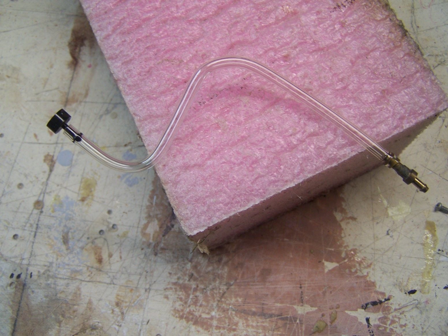
I was concerned about heating the 4mm fuel line to help it over fittings. It seem once heated it changes and becomes rubbery. I extreme heated some and put some tight bends in it. I pressurized it with my Royobi air pump. It went past 150 psi and back to the R in Royobi on the gauge, maybe 200 psi. It held.
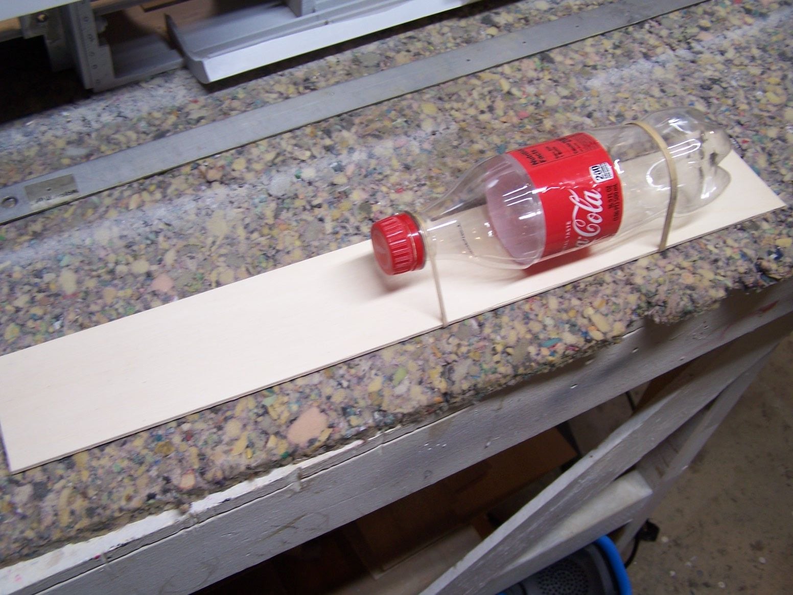
I am going to make a tray for the brake air bottle and brake valve. There is little weight to everything.
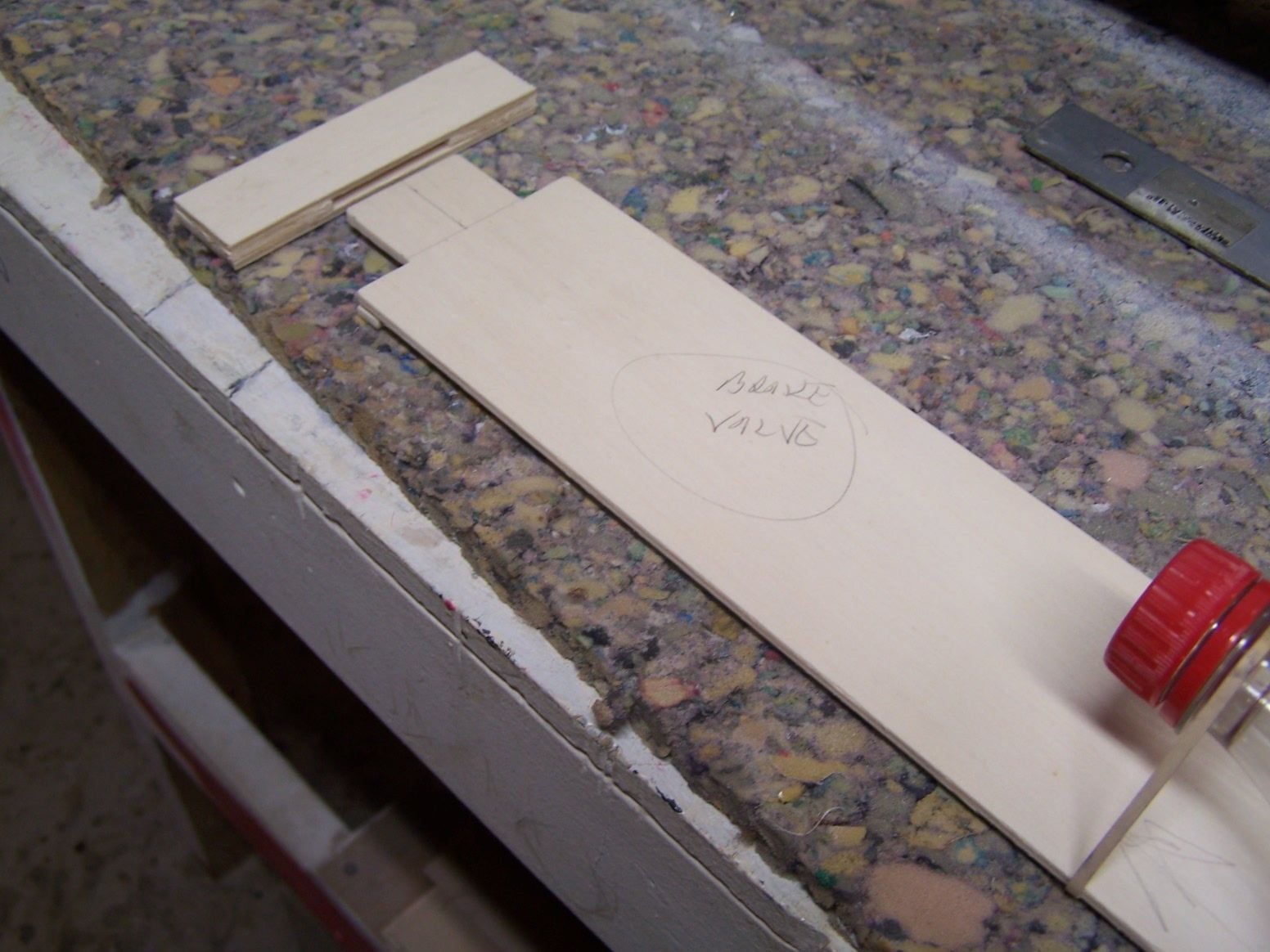
It will have a pocket on one side and a screw on the other to hold it in place.

There is a bunch of unused space above and behind the nose gear. It will be relatively accesable going in this way. Four screws holding the nose gear as opposed to EVERYTHING under the hatch.
03-31-2019, 07:52 PM
#565
Thread Starter
Join Date: Mar 2009
Location: willow springs , IL
Posts: 1,212
Likes: 0
Received 25 Likes
on
14 Posts
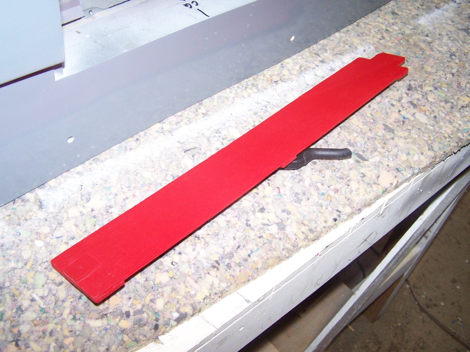
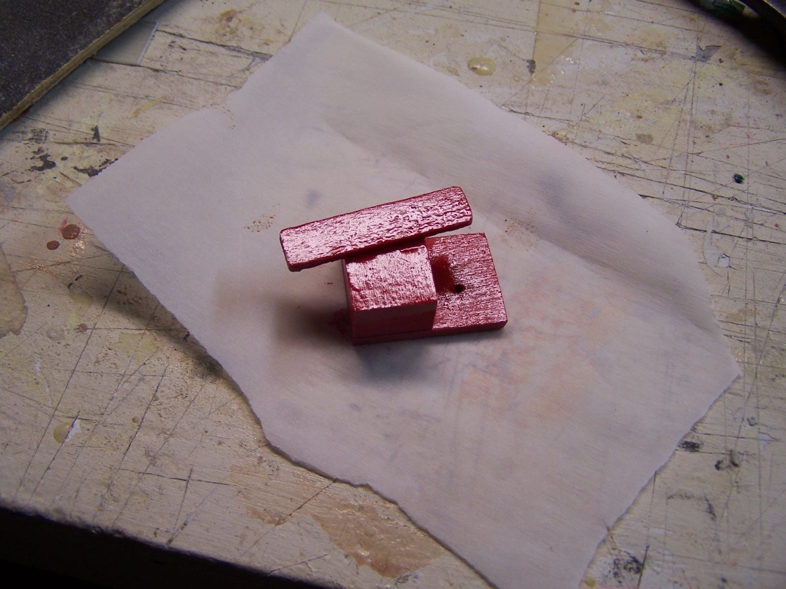
The finished tray painted red with spacers and some material for the screw to grab.
Secured with one screw under the nose retract with a plywood scab doubled under the screw head.
The pocket glued to the floor with the tongue of the tray slipped into it.
05-12-2019, 07:10 AM
#566
Thread Starter
Join Date: Mar 2009
Location: willow springs , IL
Posts: 1,212
Likes: 0
Received 25 Likes
on
14 Posts


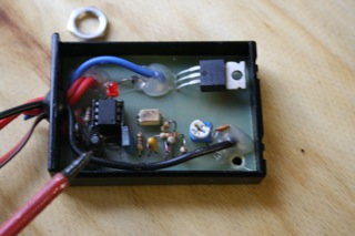
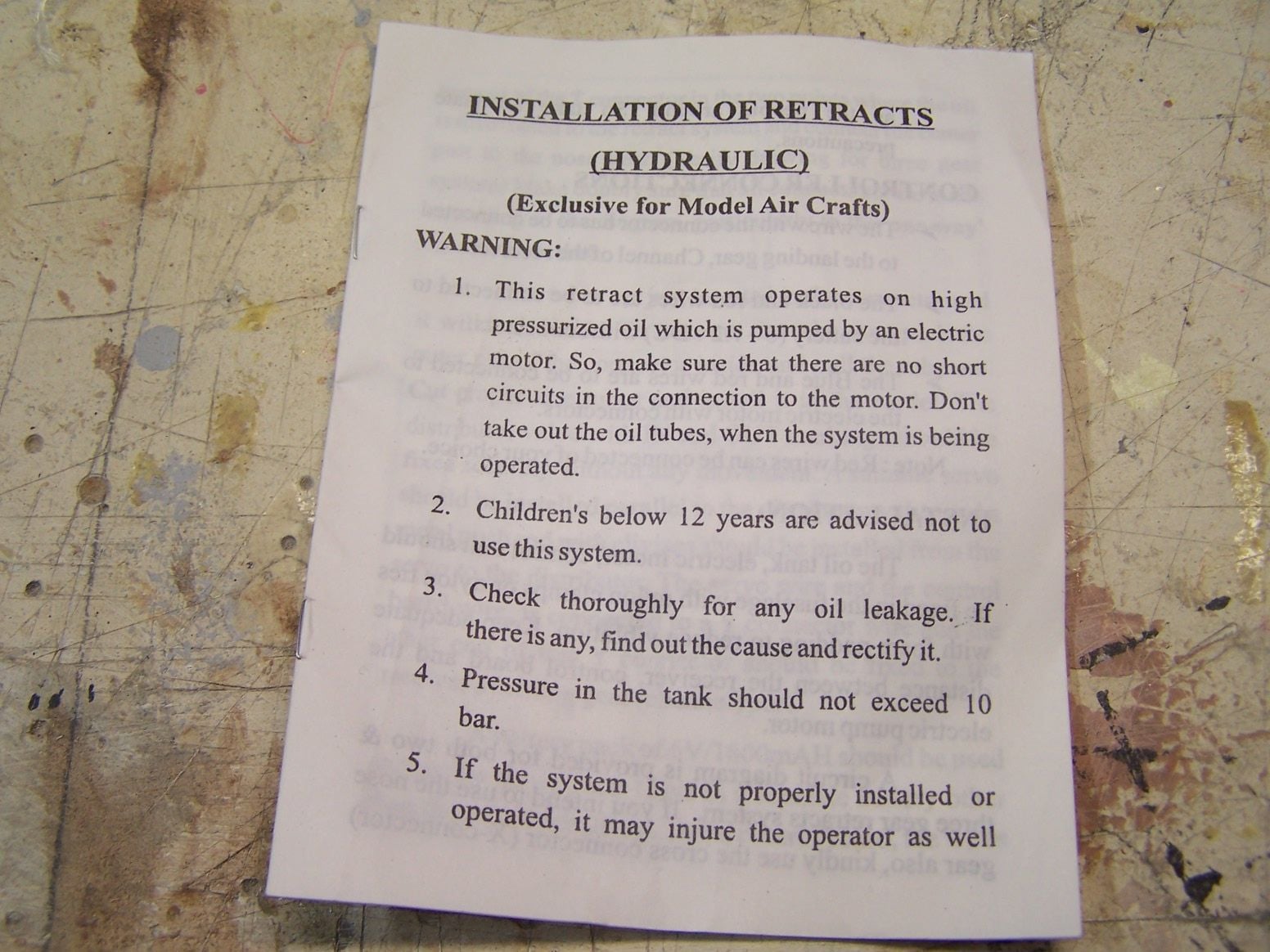
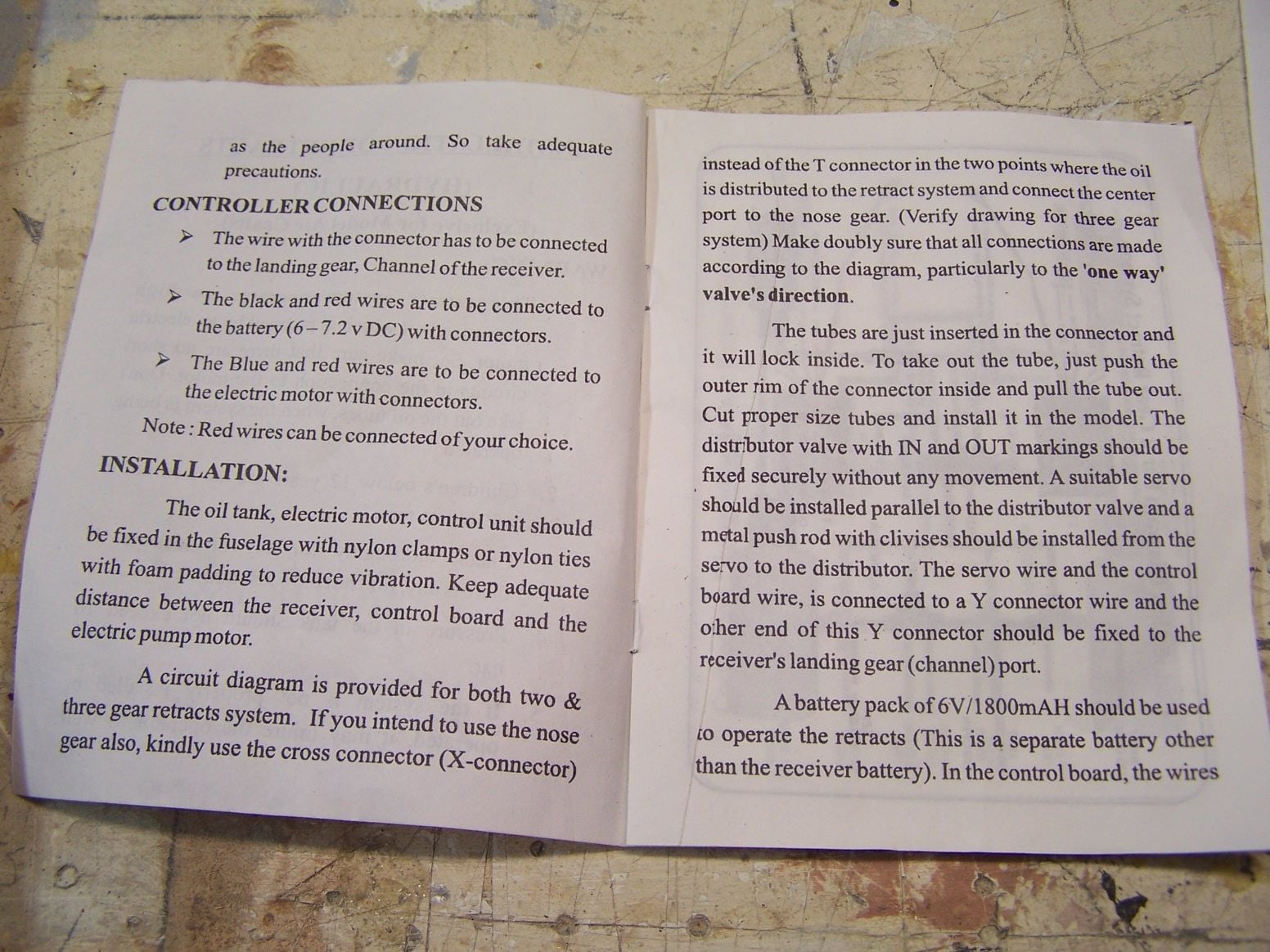
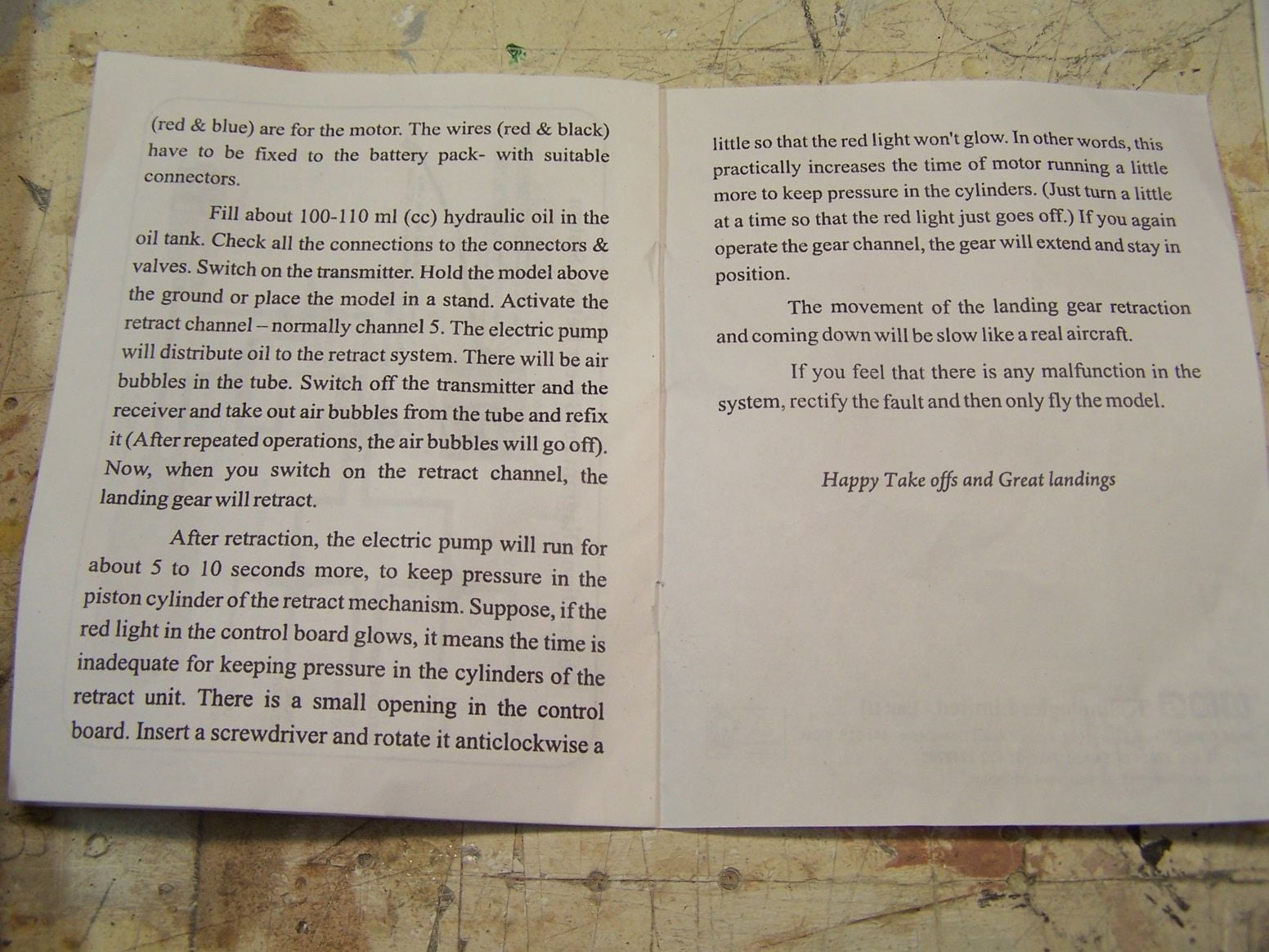
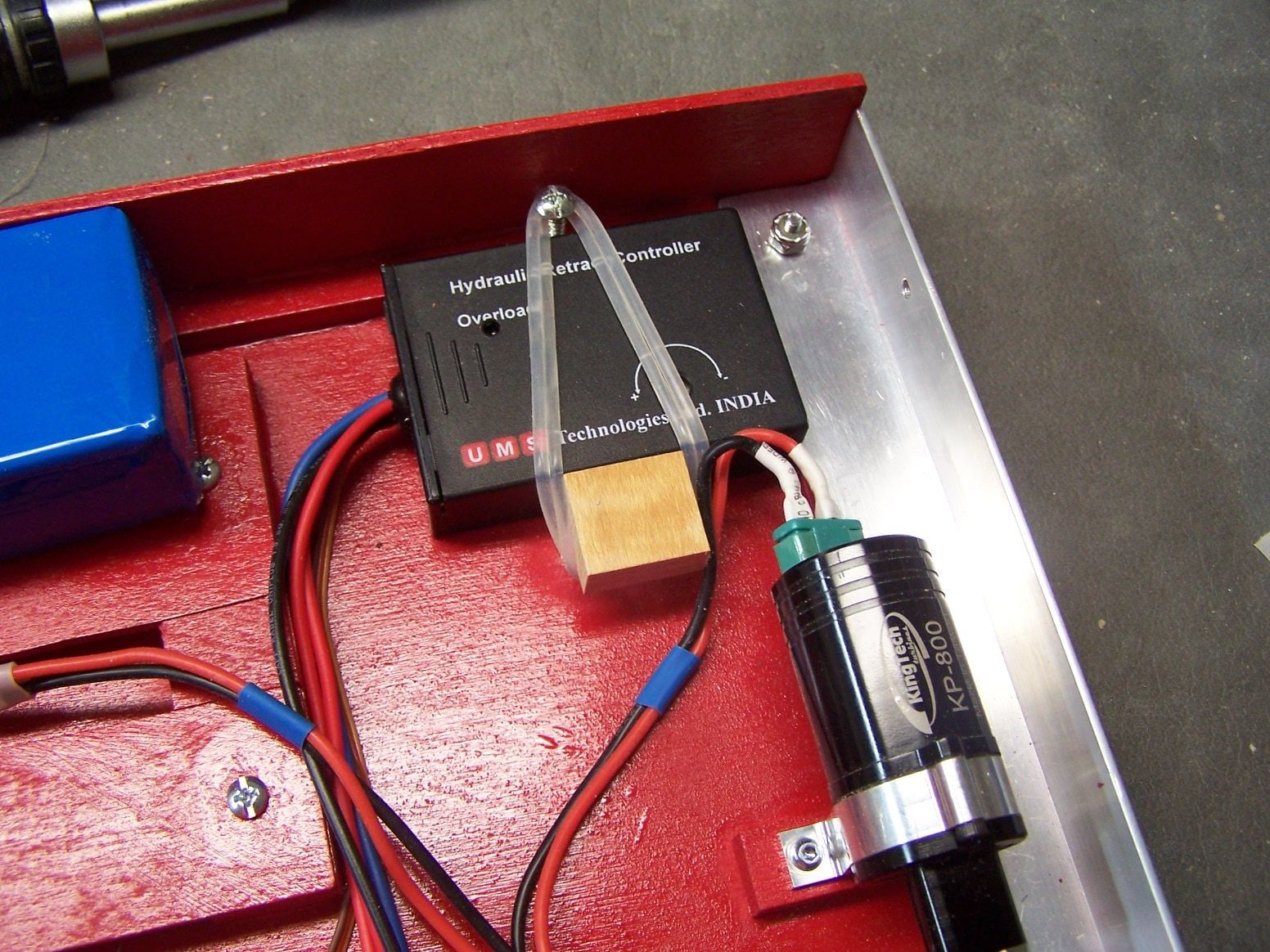
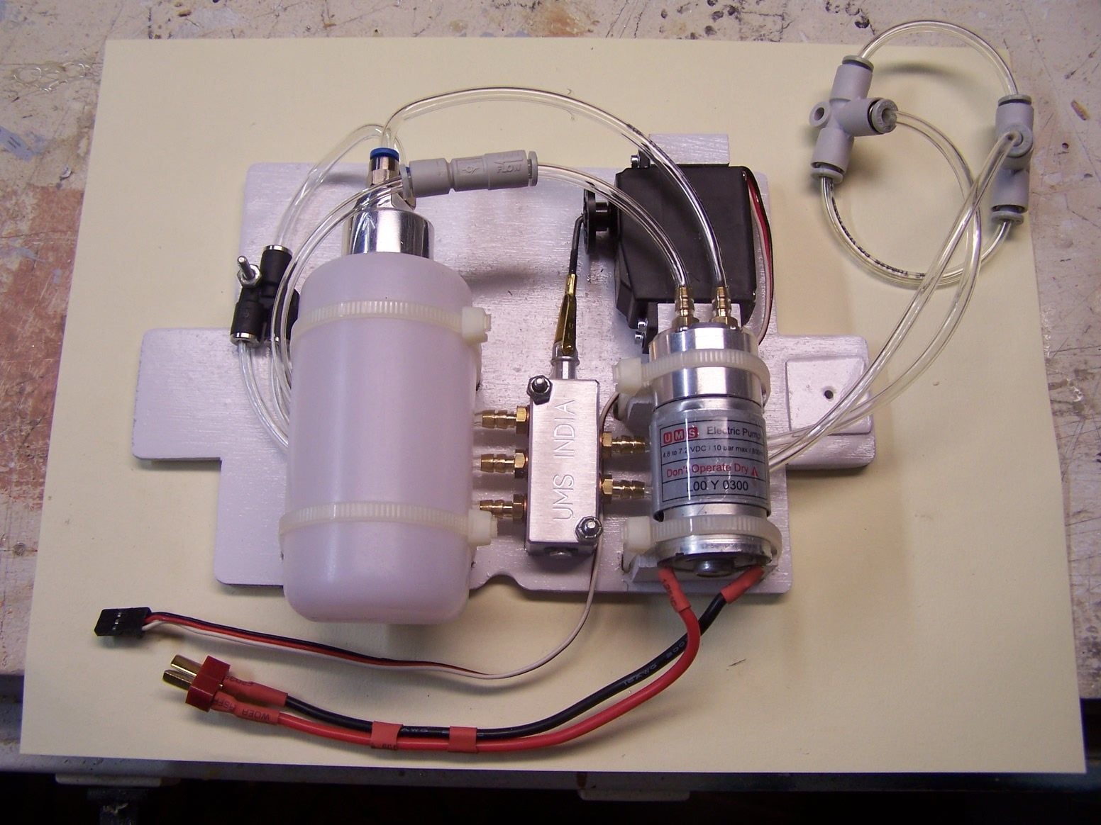
Here is a hydraulic retract controller I got from my friend. It is made in India by a company called USM and used to be sold by Hobby King. It doesn't seem like you can buy them any longer. I may find out why.

 05-14-2019, 06:40 PM
#568
Thread Starter
Join Date: Mar 2009
Location: willow springs , IL
Posts: 1,212
Likes: 0
Received 25 Likes
on
14 Posts
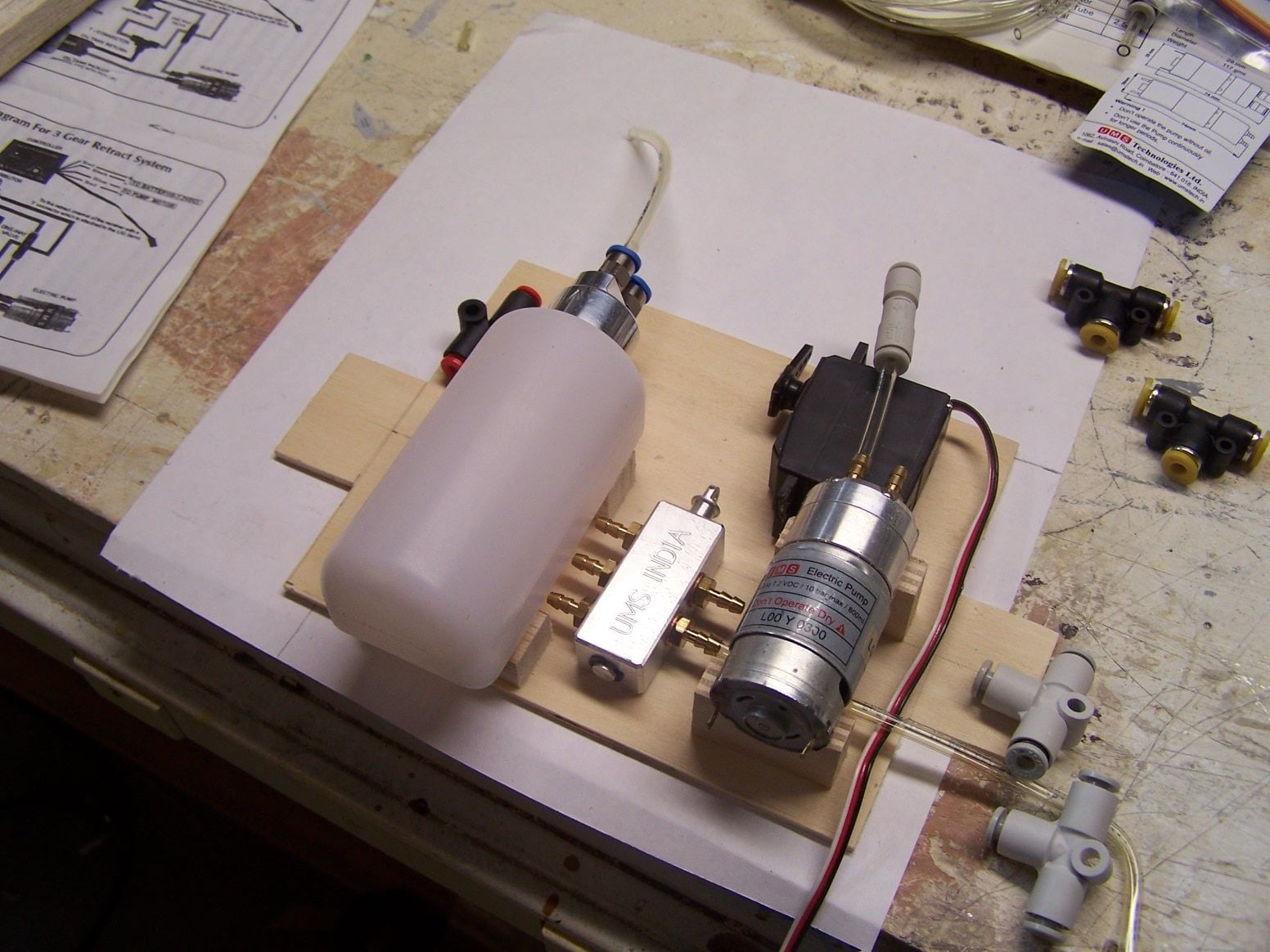
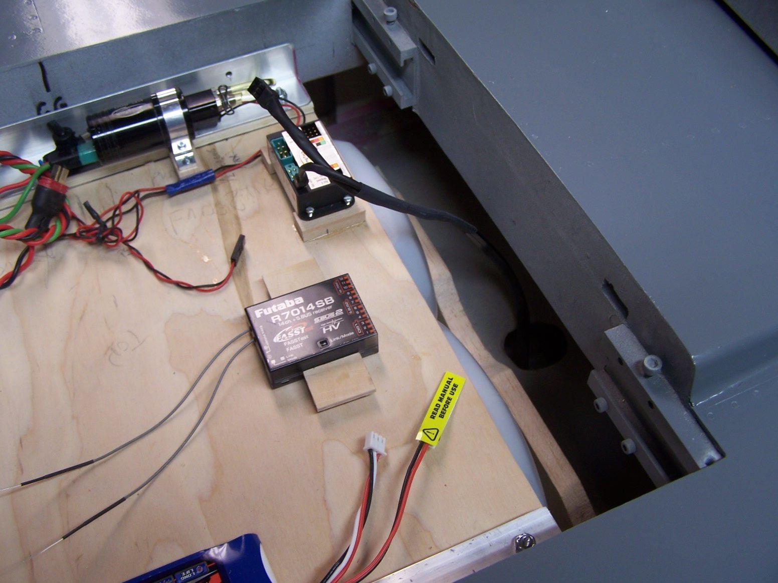
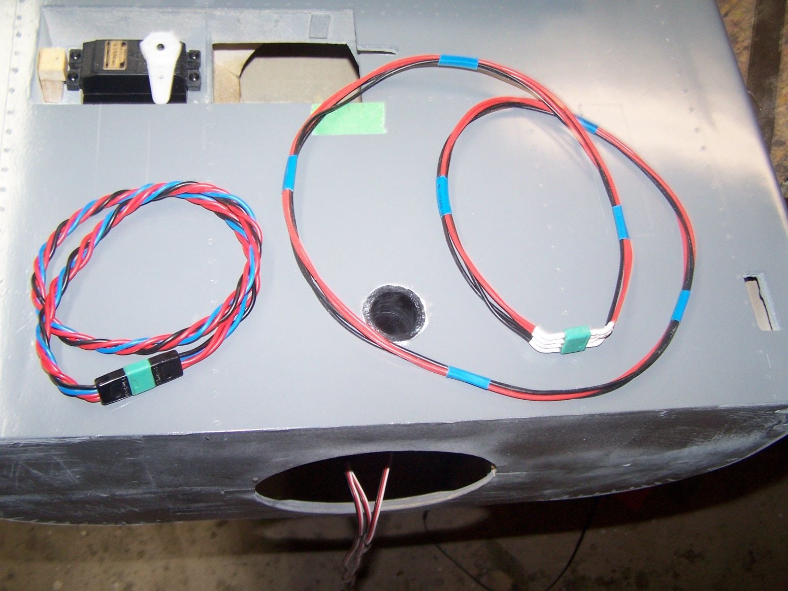
This is the preliminary lay out for the for the hydraulic system. the hoses will run under the tank and pump. The tray will go in the wheel well between the wheels. The controller will go up on the radio tray.
05-18-2019, 09:50 PM
#569
Thread Starter
Join Date: Mar 2009
Location: willow springs , IL
Posts: 1,212
Likes: 0
Received 25 Likes
on
14 Posts
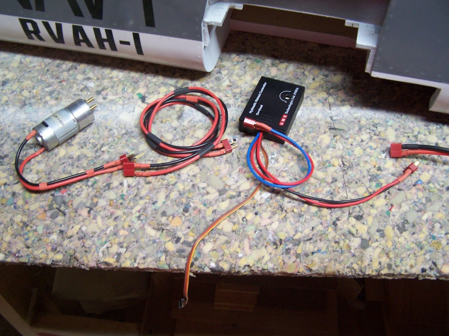
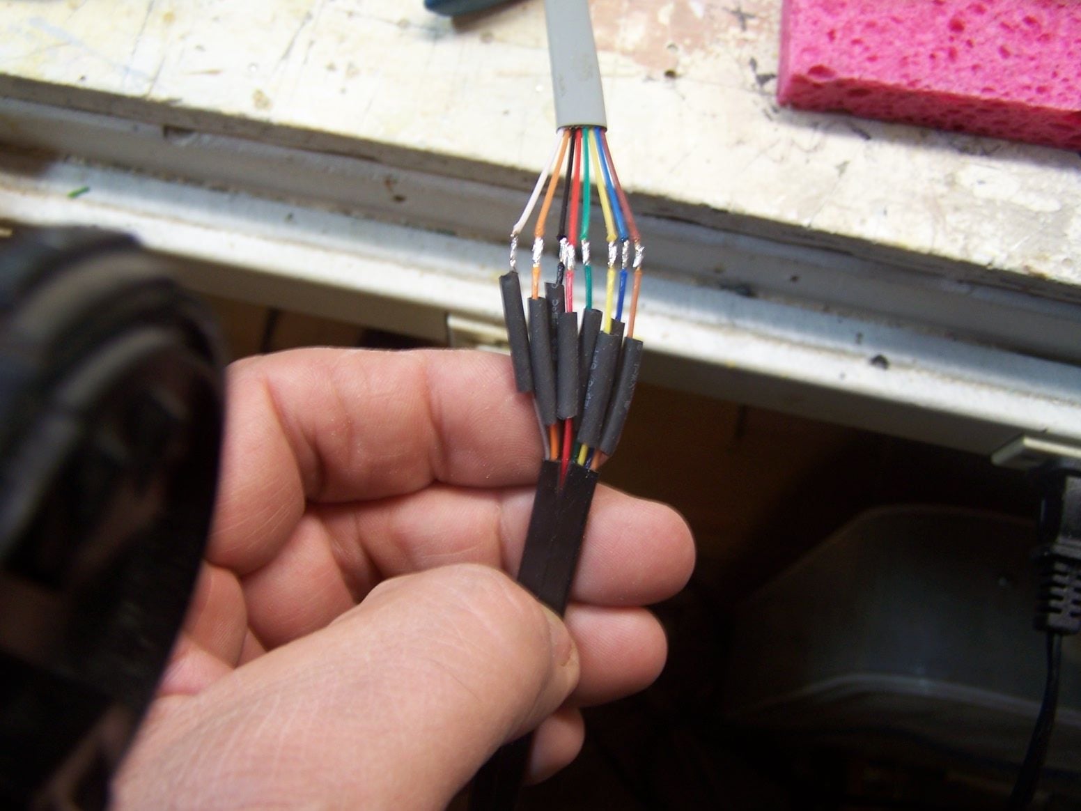
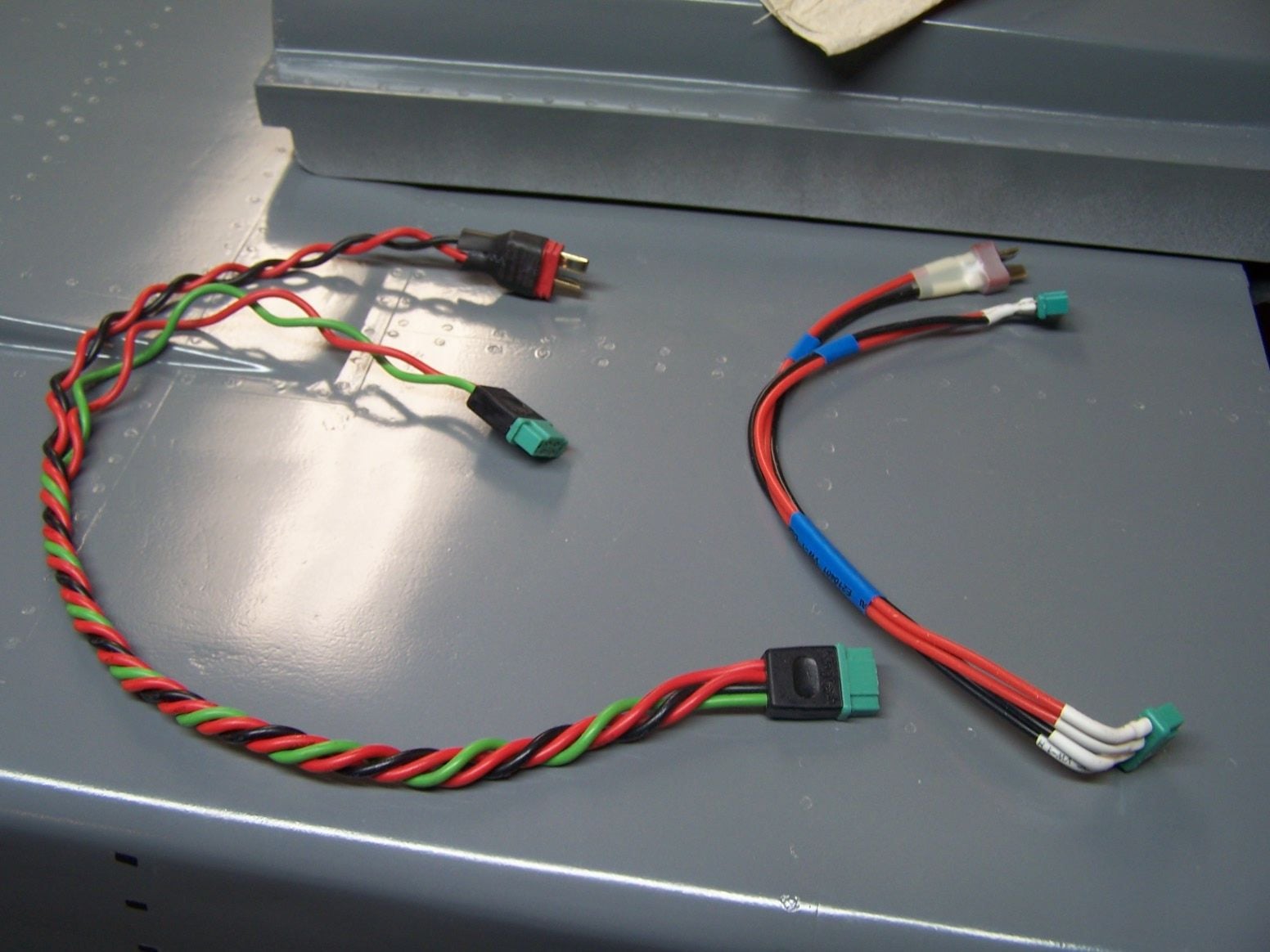
I put plugs on everything and made an extension for the retract controller
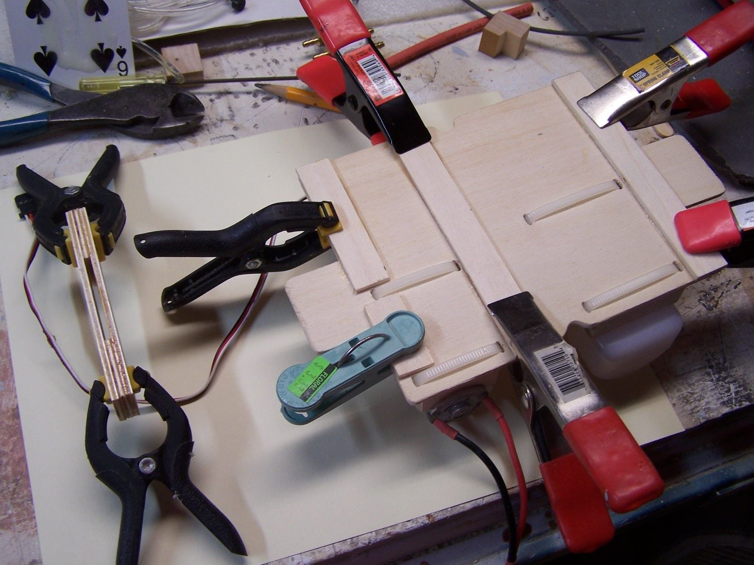
some standoffs on the bottom of the hydraulic pump tray for the zip ties and nose steering extension to clear
The extension for the nose steering will run under (over) the tray.
The tray sitting where it will be installed. I won't use the pocket and screw to hold it. It will be held in with two screws.
The hydraulic retract controller will mount on the top tray.
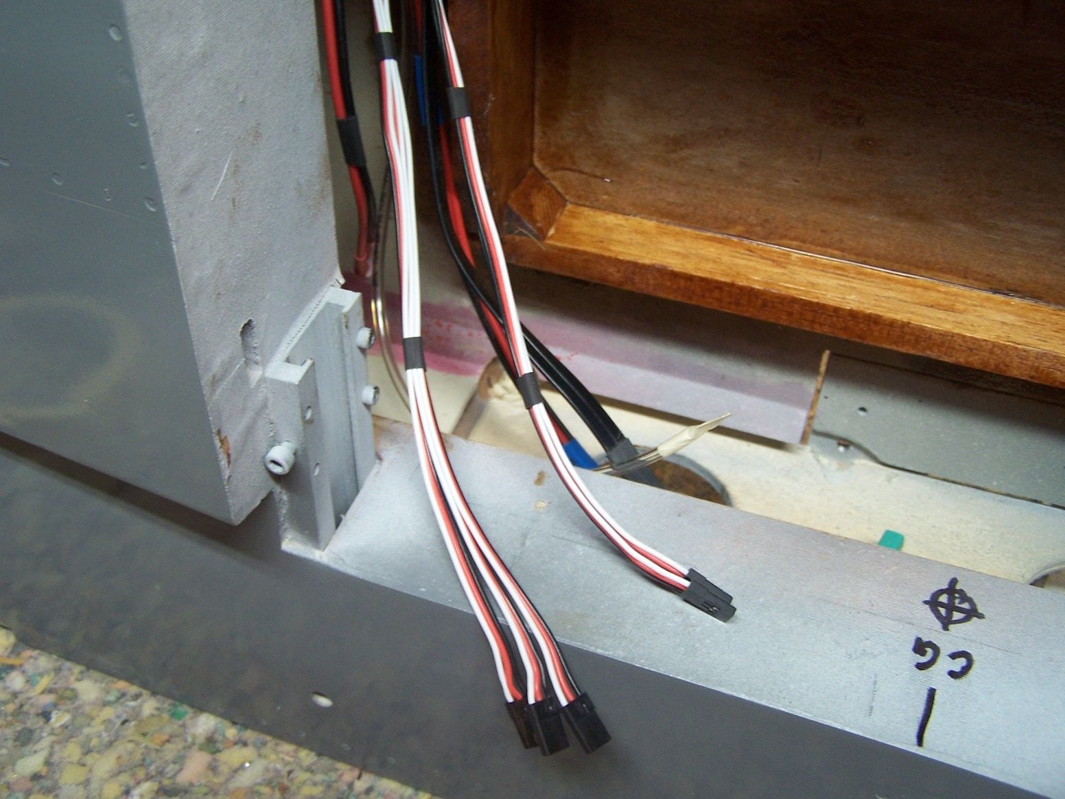
A little heat shrink. The three extensions go to the tail flight controls and the two go forward for the steering and the hydraulic directional valve.
A little Tee
As flush as I could think of to zip tie everything down in front of the turbine.
 06-20-2019, 10:54 AM
#574
Thread Starter
Join Date: Mar 2009
Location: willow springs , IL
Posts: 1,212
Likes: 0
Received 25 Likes
on
14 Posts
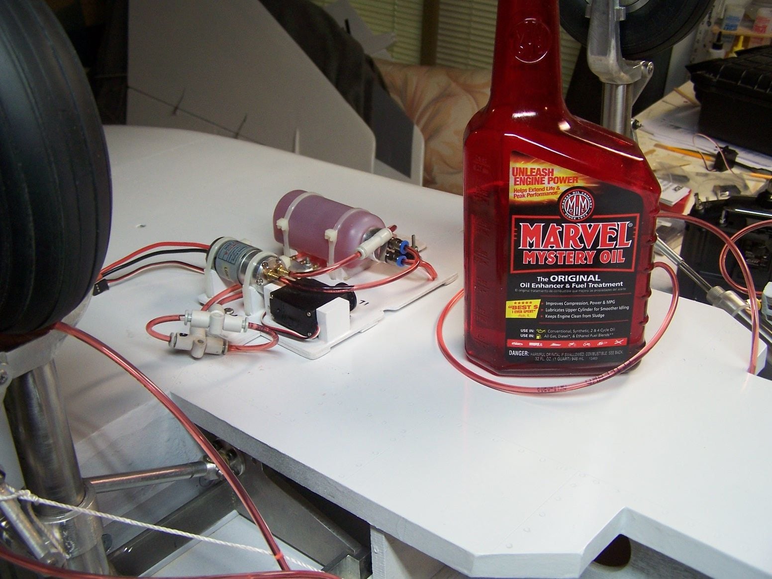
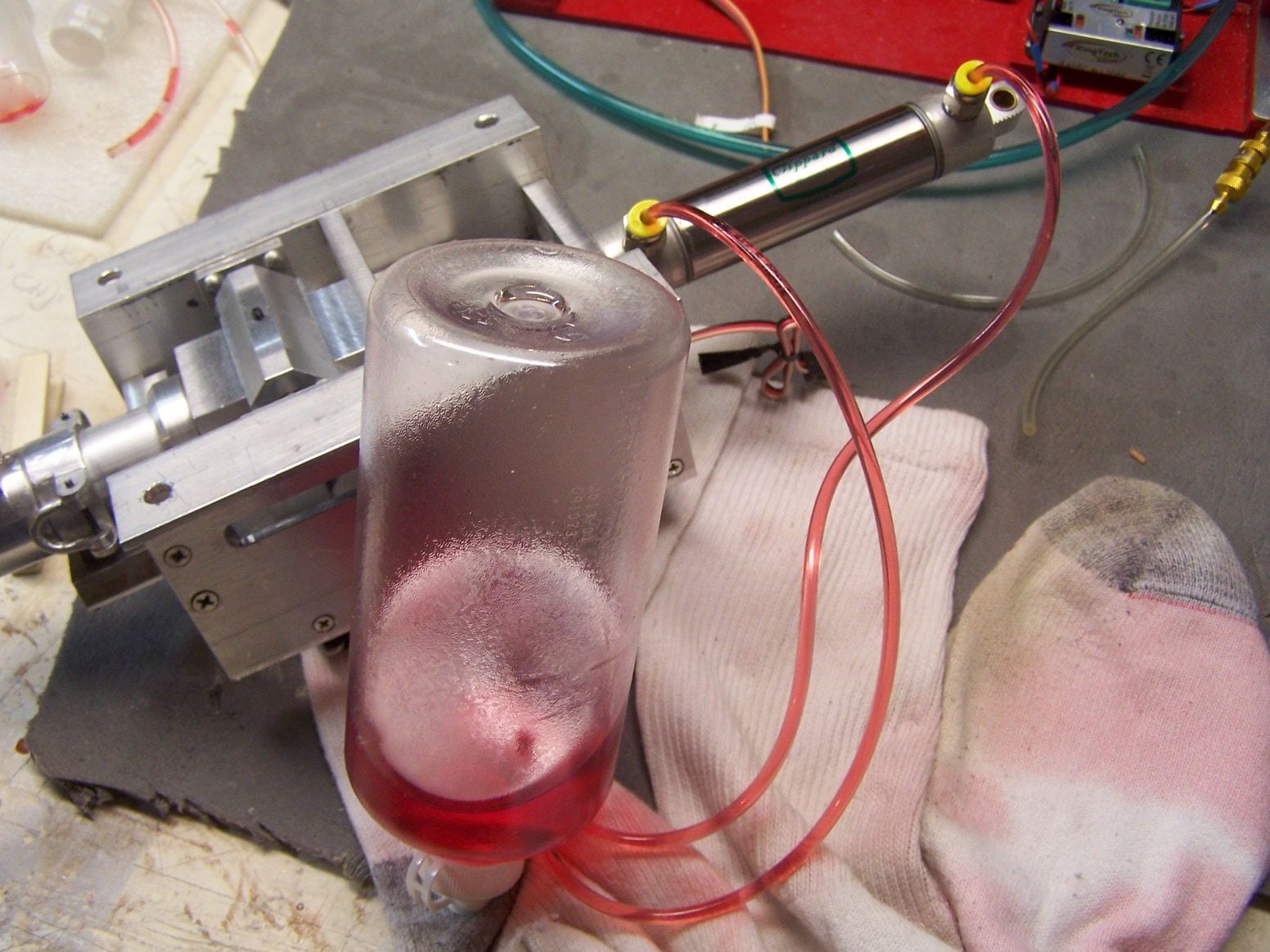
I filled the pump and reservoir with oil and ran the pump to circulate the oil. For the cylinders I made a bottle to plug the lines into and then cycle the cylinders to eliminate the air. It took a couple of cycles in different orientations to get the air out. Im sure connecting the system will reintroduce a small amount of air. At that point it will be a matter of playing with it to get the air out. Im using MMO in the system. The nice thing about the red color is an air bubble is very easy to see.
06-21-2019, 03:40 AM
#575


In regard to the UMS system, you should check the Jet Legend Mig-29 thread. There was a bad capacitor in the controller that needs to be replaced. You will need to identify if your controller was already fiixed or not. See on of the post of the thread here : http://www.rcuniverse.com/forum/10217505-post193.html
I have one of those Mig-29 and stopped flying it due to the gear issue. I have the UMS system but my valve are leaking. Im now going to use a system from Spain (https://www.magomhrc.com/en/13-hydraulic-parts)
Good luck!
Edgar